

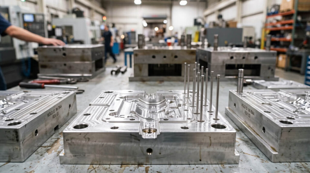
Most of the problems that show up on a molding floor were actually decided weeks earlier, on a screen. A wall that’s too thick in one spot. A wall without enough taper to release cleanly. A clip designed with zero thought for how the steel around it has to move. None of these are molding problems. They’re design decisions that molding just happens to expose.
The good news is that the physics behind injection molding is consistent enough to write down as rules. Get wall thickness, draft, and undercuts right at the CAD stage, and most of the defects buyers worry about — sink marks, warping, short shots, mold damage — simply don’t happen. Here’s what actually matters for custom plastic injection molding projects, and where a proper DFM review fits into the process.
Two Rules That Prevent Most Molding Defects: Wall Thickness and Draft
If you only apply two rules before sending a part to quote, make it these two. Together they prevent the majority of cosmetic and structural defects we see on new designs.
Keep Wall Thickness Uniform — and Within Material Limits
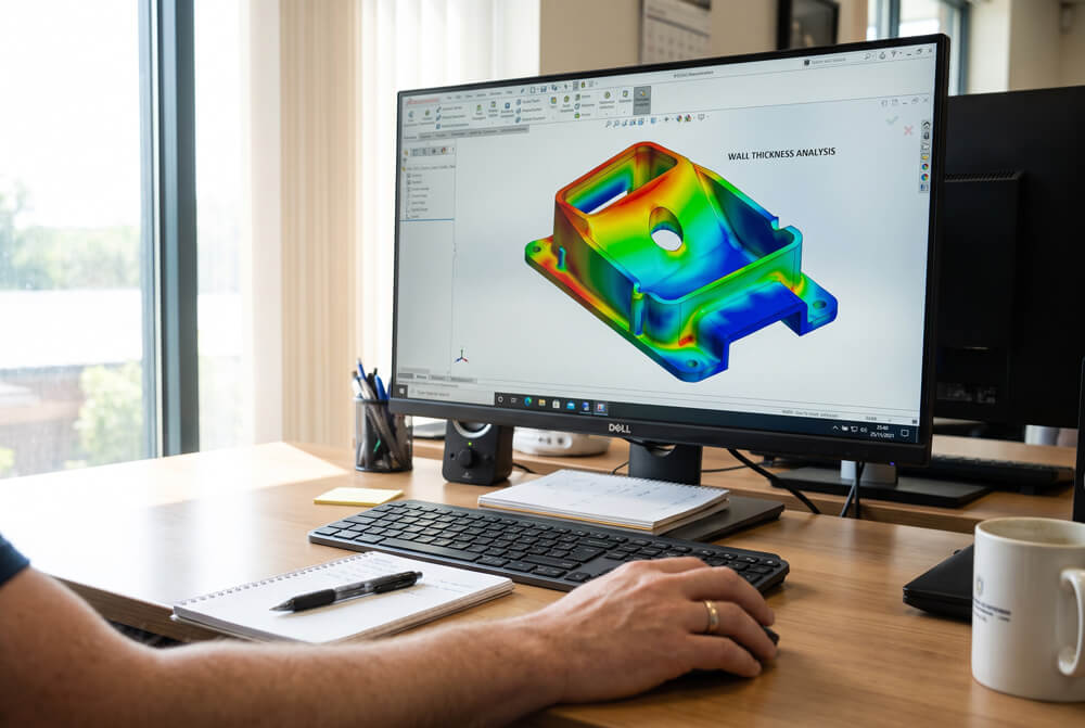
Thick sections cool slower than thin ones. As the thick section keeps shrinking after the surface has already solidified, it pulls the skin inward — that’s what a sink mark actually is. Uneven thickness next to it makes things worse, causing warp and visible weld lines where two flow fronts meet at different temperatures.
| Material | Typical Range | Practical Minimum |
|---|---|---|
| ABS | 1.2 – 3.5 mm | ~0.8 mm |
| Polycarbonate (PC) | 1.0 – 3.8 mm | ~1.0 mm |
| Polypropylene (PP) | 0.6 – 3.8 mm | ~0.5 mm (high-flow) |
| Nylon (PA) | 0.7 – 3.0 mm | ~0.7 mm |
On top of the material’s own range, hold every wall within about 25% of your part’s nominal thickness for amorphous resins like ABS and PC — tighten that to roughly 15% for semi-crystalline materials like nylon, PP, and POM, which shrink more and are less forgiving of variation. Where thickness genuinely has to change, transition gradually — a 3:1 taper ratio between the thick and thin sections avoids the abrupt shrinkage jump that causes stress cracking.
Give Every Vertical Surface Enough Draft to Release Cleanly
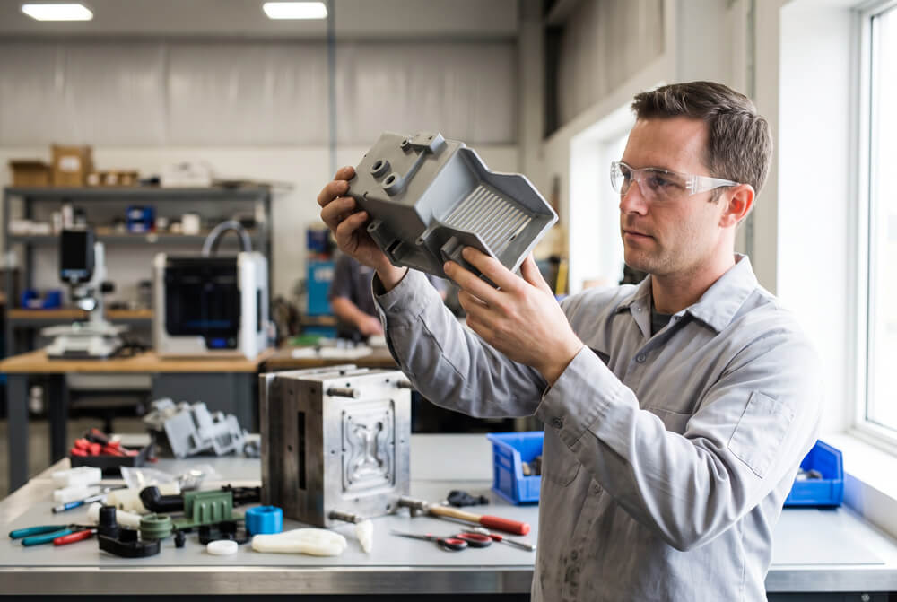
Draft is the small taper on any wall parallel to the direction the mold opens. Without it, the part drags against the steel on ejection — that friction shows up as drag marks, scuffed cosmetic surfaces, or in bad cases, a part that won’t release at all.
- Smooth (polished) surfaces: 0.5°–2° minimum per side, applied to every wall parallel to the pull direction
- Deep features: add roughly 1° for every additional inch (25 mm) of depth beyond the first 1–2 inches
- Textured surfaces: add about 1°–1.5° of draft for every 0.001 in (0.025 mm) of texture depth, on top of the baseline
- Shut-offs (metal sliding on metal): 3° minimum, non-negotiable, to protect the tool from wear
A leather-grain or heavily textured finish can push required draft to 10° or more in some areas — which is worth knowing before, not after, you’ve locked in an aggressive cosmetic texture on a tall, mostly-vertical part. Our mold-making team runs a full draft analysis against your chosen finish as part of every DFM review, so this gets flagged before tooling — not after the first T1 shot sticks in the cavity. (Source: Protolabs, Draft Angle Guidelines)
The Most Cost-Effective Way to Redesign Undercuts Without Inflating Mold Cost
An undercut is any feature that blocks the part from pulling straight out of the mold — a side hole, a snap hook, an internal thread, a recessed clip. Every undercut needs some kind of release mechanism, and those mechanisms are priced in a fairly predictable order, cheapest to most expensive:
1. Redesign or eliminate — $0 added tooling cost. A shut-off (a hole placed directly below a snap-fit or tab) lets solid steel form the feature with no moving parts. A living hinge can often replace an external snap. This is always the cheapest fix, when the function allows it.
2. Lifter — roughly $3,000–$7,000 per cavity. An angled pin that releases internal undercuts, like inward-facing snap-fits or ribs, as the mold opens. Cheaper and more compact than a full slide.
3. Side-action slide — roughly $3,000–$10,000+ per slide. A block that retracts sideways to release external undercuts, like side holes or ports. Necessary when there’s no way to redesign the feature away, but the most expensive of the three.
A few things worth knowing before you commit to a mechanism:
- Two undercuts typically cost around 50% more in added tooling than one; three or more can add 100–200% versus an undercut-free design — so consolidating or eliminating features pays off fast.
- Position undercuts on the same side of the part where possible. One slide covering three features costs far less than three separate slides.
- For soft, flexible resins (PP, PE, TPE) with shallow undercuts — roughly 2% interference or less — forced ejection can sometimes eliminate the mechanism entirely, letting the part flex briefly during ejection.
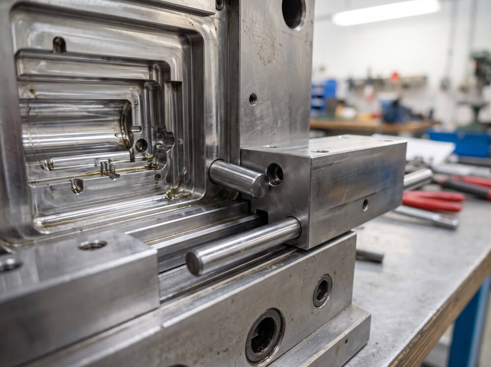
A well-run DFM review catches undercuts before they’re locked into a design, and can cut undercut-related tooling cost by roughly 20–40% just by flagging which features can be simplified or eliminated. That review is worth having before you finalize geometry, not after a quote comes back higher than expected. (Source: Zetarmold, Injection Mold Undercut Design Guide)
How a Free DFM Review Catches Catastrophic Molding Flaws Before You Cut Steel
A real DFM (Design for Manufacturability) review isn’t a checkbox — it’s a working audit of the CAD file against everything above, plus a few things that are much harder to catch by eye:
- Gate location and flow path — where molten resin enters the cavity, and whether it reaches every section before starting to cool
- Wall thickness uniformity — flagged against the material-specific ranges and tolerance rules above
- Draft angle audit — every vertical face checked against the chosen finish and texture
- Undercut mapping — every feature that blocks straight ejection, flagged with a recommended fix
- Weld line and air trap prediction — where two flow fronts meet, and where air can get trapped instead of venting out
- Ejector pin placement — confirming the part can actually be pushed out without deforming or leaving visible pin marks on a cosmetic surface
The value of catching these on a screen instead of in steel isn’t abstract. A design flaw flagged during DFM costs nothing more than a CAD revision. The same flaw discovered after the cavity is cut turns into a machining job — new steel removed, new EDM work, a new T1 trial run — on a schedule that’s already committed. That’s the entire argument for doing this review before quoting tooling, not after.

Every quote we send at YG includes a full DFM report — gate placement, wall thickness check, draft audit, and undercut flagging — through our ISO 9001-certified quality assurance process, before steel is ever discussed. If you have a design you’re not fully confident in, send us the CAD file and we’ll tell you honestly what needs to change and why.
None of these rules are complicated on their own. What catches people is applying all of them together, on a real part, before a quote gets sent — which is exactly what a proper DFM pass is for.
Frequently Asked Questions
What is the minimum wall thickness for injection molding?
It depends on the resin, but most engineering plastics have a practical floor between 0.5 mm and 1.0 mm.
- ABS: roughly 0.8–1.2 mm minimum, 1.2–3.5 mm typical range
- Polycarbonate (PC): roughly 1.0 mm minimum, 1.0–3.8 mm typical range
- Polypropylene (PP): as thin as 0.5 mm on short flow paths thanks to high flow
- Nylon (PA): roughly 0.7 mm minimum, tighter tolerance needed due to shrinkage
How much draft angle is required for injection molded parts?
A baseline of 0.5°–2° per side on smooth surfaces, more as depth or texture increases.
- Polished, smooth surfaces: 0.5°–2° minimum
- Textured surfaces: add ~1°–1.5° per 0.001 in (0.025 mm) of texture depth
- Deep features: add ~1° per additional inch of depth beyond the first 1–2 inches
- Metal-on-metal shut-offs: 3° minimum, no exceptions
What are the basic rules of DFM in injection molding?
A short checklist covers most of what determines whether a design is moldable as drawn.
- Keep wall thickness uniform, within material-specific ranges
- Apply adequate draft angle to every vertical surface
- Add generous fillets at inside corners — at least 25% of wall thickness — to reduce stress concentration
- Size ribs and gussets at 40–60% of nominal wall thickness to avoid sink
- Design bosses with a base diameter roughly 2–3x the screw diameter, walled at the same 40–60% rule
- Minimize or eliminate undercuts before accepting a slide or lifter as the default fix
How do you avoid sink marks in injection molding design?
Keep any feature attached to a wall — ribs, bosses, gussets — noticeably thinner than the wall itself.
- Size ribs and bosses at 40–60% of the adjoining wall’s nominal thickness
- Core out naturally thick, solid sections instead of leaving them as solid blocks
- Use a gradual transition (roughly 3:1 taper) anywhere thickness has to change
- Round inside corners instead of leaving sharp intersections, which concentrate both stress and shrinkage
Why are ribs and gussets used in injection molding instead of increasing wall thickness?
Because stiffness scales with thickness cubed, not linearly — a rib adds more strength per gram than a thicker wall.
- Doubling wall thickness more than doubles bending stiffness, but also more than doubles cooling time and cycle cost
- Thicker solid walls are far more prone to sink marks and internal voids
- A properly sized rib (40–60% of wall thickness) adds targeted stiffness without the cooling penalty or sink risk of a uniformly thicker part
Can injection molded parts have internal threads?
Yes, in three common ways, each with a different cost and strength trade-off.
- Molded-in metal inserts — placed in the mold before injection; highest pull-out and torque strength, but the most expensive method due to insert placement and tooling.
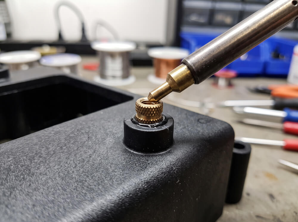
- Heat-set or ultrasonic brass inserts — pressed into a molded hole after the part is made; strong, widely used, and a good balance of cost and holding power.
- Directly molded plastic threads — formed by an unscrewing mold mechanism; cheapest per part at volume, but adds tooling complexity and cycle time, and plastic threads wear faster under repeated fastening than a metal insert.
Not sure if your design is ready for tooling?
Send us your CAD file — our engineering team will run a full DFM review covering wall thickness, draft, and undercuts, and send back an honest report before any steel is quoted.
Get a Free DFM Review