

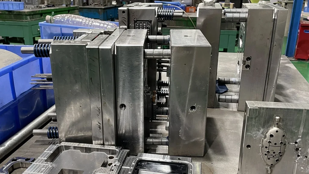
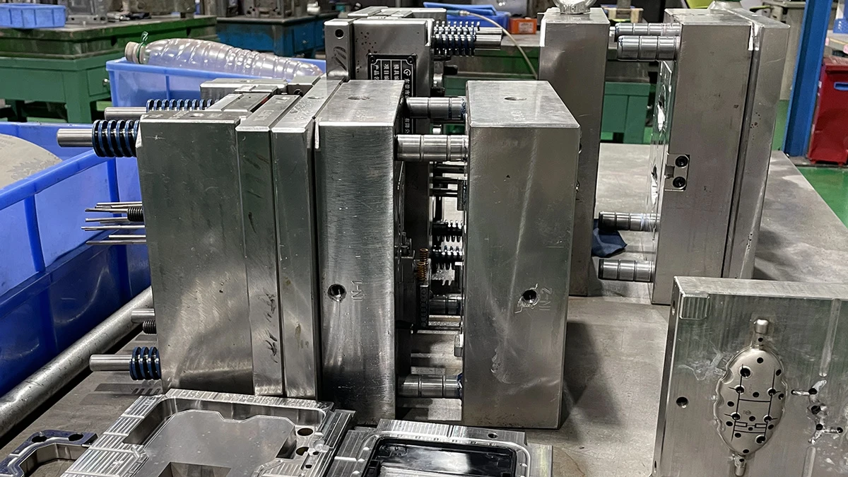
If you’re building a real product — not a one-off gift, a genuine accessory meant to sell — at some point “get a mold made” stops being a line item and starts being a project you need to actually understand. Most guides to this either stay too abstract to be useful or drown you in machinist jargon. This one is written for the founder in between: someone building a $30–$70 accessory through custom plastic injection molding, ordering in the thousands rather than the millions, who needs to know enough to ask the right questions and catch a corner-cutting supplier before it costs them a production run.
Here’s what actually happens between a finished CAD file and a mold that’s ready to run.
The Process, at a Glance
DFM Review
Steel & Base Order
Rough Machining
Heat Treatment
CNC / EDM Finishing
Fitting & Polish
T1 Trial
Why Custom Molds Should Be Built on Standardized Components — Not Proprietary Parts
Inside every mold sits a set of wear parts that fail on a schedule, not by accident: ejector pins, guide pillars and bushings, springs, locating rings. These take the mechanical abuse of every single cycle, and eventually one of them breaks. The question that actually matters is what happens next.
Three internationally recognized systems cover the vast majority of mold hardware: DME (American-origin, primarily imperial sizing), HASCO (European-origin, metric), and LKM (Chinese-origin, widely stocked and compatible with both). Building to one of these standards means a broken ejector pin is a same-week fix from a local distributor almost anywhere in the world. Building to a shop’s own proprietary dimensions means that same broken pin sends you back to the original mold maker — possibly on the other side of the planet — for a part that may take weeks to arrive.
This isn’t a hypothetical. A mold built to DME spec but running on a HASCO-standard molder can leave a local distributor without the right pins in stock, adding real downtime to a live production line. Mismatched guide pillar dimensions between standards can force an adapter plate and a week’s delay before the fix. The safest move is simple: specify the standard in your PO, matched to where the mold will actually run, and confirm your supplier can build to it. (Source: Peifeng Precision, Mold Base Standards Explained)
We build every mold to DME, HASCO, or LKM specification by default and confirm it in the quotation — a small detail on day one that saves a client-side headache eighteen months later. Our mold-making team can advise on which standard fits your target market before tooling starts.
When EDM Is Mandatory, Not Optional, Over CNC Milling
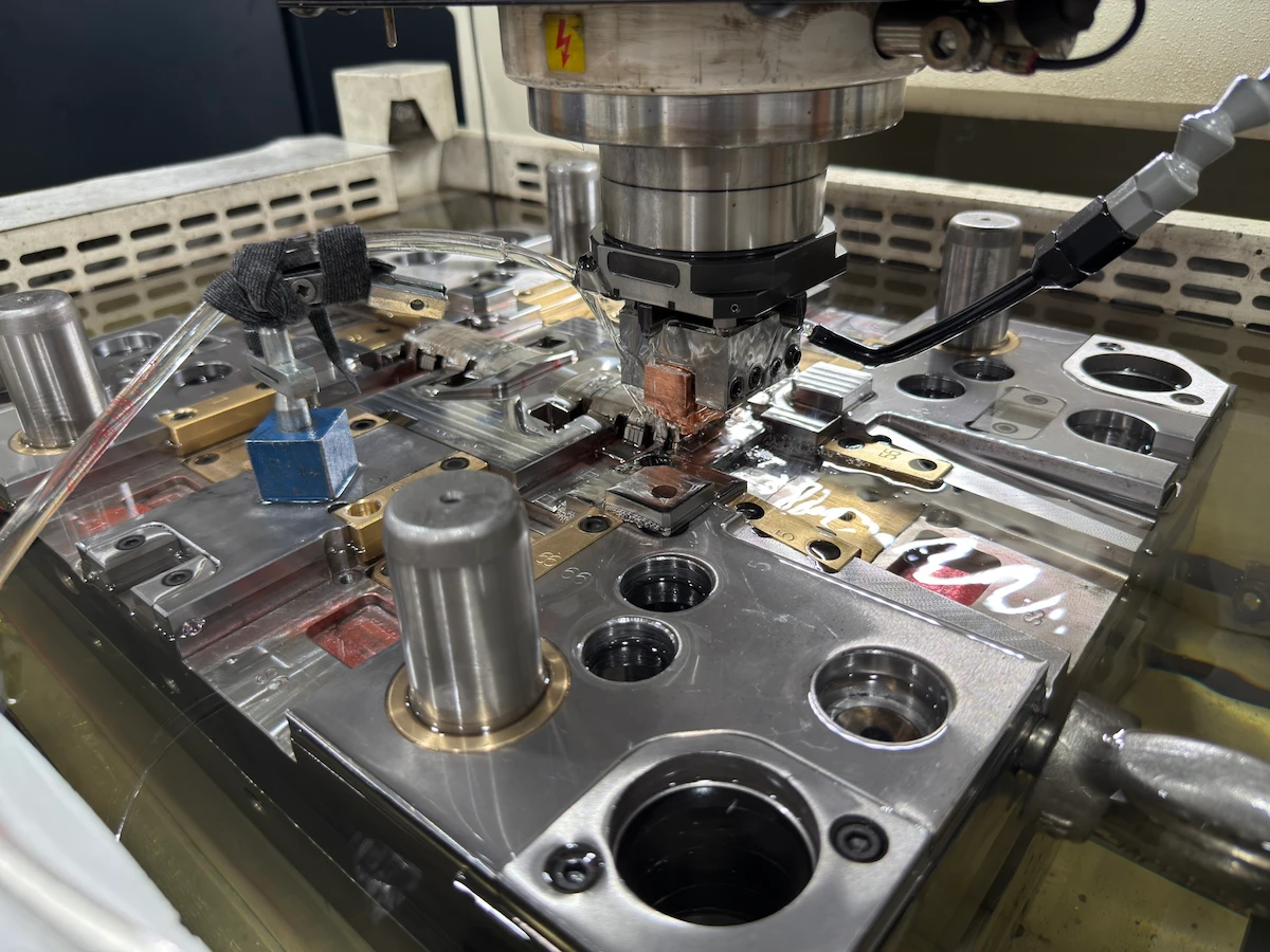
A CNC cutter is a rotating tool — which means it physically cannot produce a sharp internal corner; there’s always some minimum radius left behind by the tool itself. It also struggles with deep, narrow slots where the cutter can’t reach without deflecting or breaking. For a lot of geometry, that’s a non-issue. For sharp-cornered snap features, fine ribs, or a specific spark-eroded cosmetic texture, it’s a hard limit — and this is where EDM (electrical discharge machining) stops being optional.
- Sinker EDM uses a shaped electrode to erode a precise cavity feature into hardened steel — the only practical way to produce sharp inside corners, fine detail, or a true spark-textured cosmetic surface.
- Wire EDM threads a thin wire through the steel like an extremely precise bandsaw — essential for slide and lifter components, ejector blade slots, and clean through-cuts in steel that’s already been hardened.
A shop without both machines in-house has two options when a design calls for a feature it can’t cut: subcontract it out (adding time and a second party to coordinate), or quietly round the corner and hope you don’t notice. On a snap-fit for a protective case or a precision-fit accessory housing, that rounded corner is exactly the kind of compromise that shows up as a wobbly assembly months later. Cosmetic spark textures have the same problem in reverse — a true EDM-textured finish reads as intentional and premium, while a texture applied after the fact with abrasives or a generic pattern often looks noticeably flatter under angled light. Ask directly whether wire and sinker EDM are run in-house, not outsourced — it’s one of the fastest ways to separate a real tool room from a middleman.
How Cooling Channel Layout Decides Cycle Time and Warpage Before the Mold Is Even Finished
The cooling phase isn’t a minor part of the injection cycle — it typically accounts for roughly 70–80% of total cycle time. That single fact is why cooling channel layout, decided during tooling fabrication and effectively permanent once the mold is built, has more influence on your ongoing per-part cost and part quality than almost anything else in this article.
The cheap, fast approach is a straight-drilled channel: bore a hole through the steel block in a straight line and move on. It works fine on simple, flat geometry. On a part with ribs, bosses, or varying wall thickness, straight channels leave some areas close to the coolant and others far from it — those distant areas cool slower, shrink differently, and warp. The fix, if a shop doesn’t want to redesign the water layout properly, is usually to just run the cooling phase longer across the entire mold — which raises cycle time, and therefore machine-hour cost, for the entire life of the tool.
A properly designed layout — following the part’s actual geometry rather than the path of least drilling resistance — commonly cuts cooling time by roughly 20% to 40% compared to a straight-drilled equivalent, while also reducing warpage. That difference compounds over hundreds of thousands of cycles into a meaningfully different cost per part, which is exactly why it’s worth asking a shop how they approach water layout before tooling starts, not after the first T1 sample comes out warped. (Source: PatSnap, Conformal Cooling Channels Research Summary)
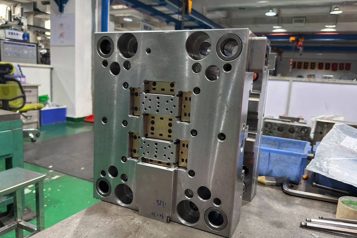
This kind of decision gets made during the mold design proposal, before any steel is cut — part of the same process discipline behind the tolerance and inspection standards in our quality assurance process.
Who We Actually Build Molds For
Everything above assumes injection molding is the right call for your project — which, under a couple hundred units, it usually isn’t. Where this genuinely pays off is a specific kind of project: a real product aimed at a defined niche, ordered in the thousands rather than the millions.
That’s deliberately the range we’re set up for. We’re not chasing a Fortune 500 account with a supply chain already locked in three vendors deep — we’re built for the founder making a structural housing for a VR headset accessory, a protective case engineered for a graded trading card or a $1,200 pair of collectible sneakers, or a storage case designed to keep a product safely out of a toddler’s reach. Simple, well-engineered plastic accessories in the $30–$70 retail range, not complex electromechanical assemblies.
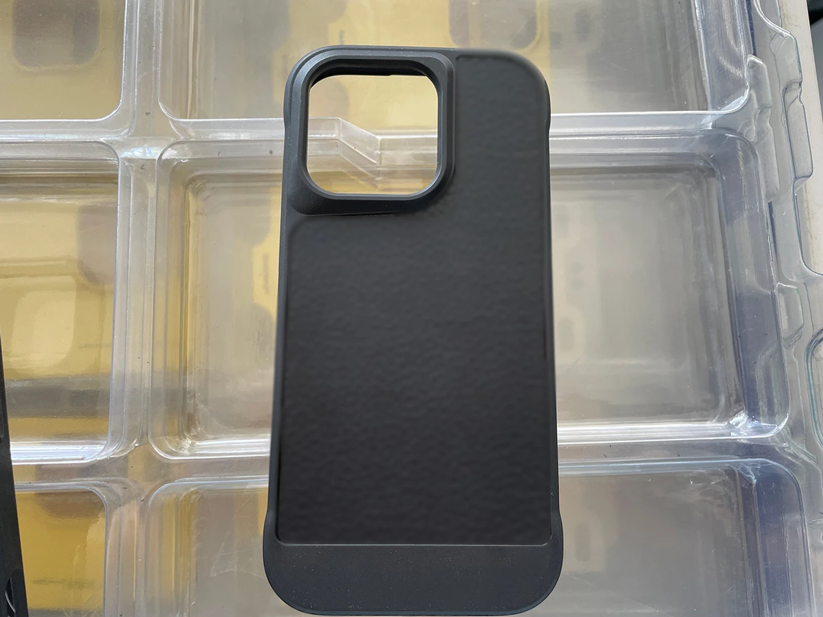
Practically, that shapes the terms we work on:
Commercial Terms
- Standard MOQ: 1,000 units
- Delivery: EXW or DDP, by preference
- Payment: 100% prepay, 50/50 split, or net-30 for repeat orders
- NDA signed before any CAD file changes hands
- Mold ownership transfers 100% to you on final payment
Technical Capacity
- 50–800 ton injection presses
- ISO Class 8 cleanroom for sensitive components
- Standard tolerance ±0.01mm
- Mold life: 300,000 shots standard, extendable to 500,000
- Production experience with PPS and other specialty resins
If something ever ships outside spec, our process is to trace it back to the actual root cause — tooling wear, process drift, a bad material lot — and work out a fix together, rather than defaulting to a straight refund and hoping it doesn’t happen twice. That approach only works if the groundwork above is solid in the first place: the right steel for the resin, standardized wear components, a cooling layout that doesn’t fight the part geometry. Cut corners on any of those, and no amount of goodwill on the back end fixes a mold that was never built right.
Frequently Asked Questions
What are the step-by-step processes to manufacture a plastic injection mold?
Seven stages, in order, from finished design to a mold ready for production.
- DFM review — checking wall thickness, draft, and undercuts against moldability
- Mold base and steel procurement — ordering the base and selecting core/cavity steel
- Rough machining — CNC roughing the cavity and core to near-final shape
- Heat treatment — hardening the steel for wear resistance
- Precision finishing — CNC and EDM work to bring features to final dimension
- Fitting and polishing — assembling the mold and achieving the specified surface finish
- T1 trial — the first real shots, checked against the design before approval
What machines and equipment are required to make a plastic injection mold?
A real tool room needs a specific set of equipment in-house — its absence is a fast way to spot a middleman.
- CNC machining centers (ideally including 5-axis capability) for cavity and core roughing and finishing
- Wire EDM and sinker EDM for sharp corners, fine detail, and textured surfaces
- Surface grinders for flat, parallel mold plates
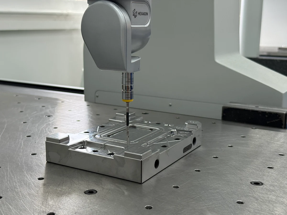
- A CMM (coordinate measuring machine) for dimensional verification against the CAD model
Can you 3D print an injection mold for low-volume plastic prototyping?
Yes, within limits — it’s a real option for early validation, not for production.
- Resin or metal 3D printed mold inserts can produce real injection-molded parts, in real resin, within days
- Shot life is typically limited to a few hundred to a few thousand parts before the insert degrades
- Good for validating fit, function, and material behavior on a few dozen to a few hundred units — not a substitute for production tooling
How long does it realistically take to build a custom injection mold?
Roughly 1 to 3 weeks for rapid bridge tooling, and 6 to 8 weeks for full production tooling.
- Rapid tooling (aluminum, single-cavity): 1–3 weeks — see our rapid tooling program for validation-stage builds
- Production tooling (hardened steel, multi-cavity): typically 6–8 weeks
- Complex geometry, multiple cavities, or design changes mid-build can extend either timeline
What is the best steel grade for mold cores and cavities?
It depends on volume, surface finish, and resin — there’s no single best grade across every project.
- P20 — 30–35 HRC pre-hardened, general-purpose, good machinability, suited to low-to-mid volume
- 718H — 35–39 HRC, better toughness and dimensional stability than P20, strong choice for complex cavities and high-volume production
- NAK80 — 37–43 HRC, excellent polishability, the default for optical or mirror-finish cosmetic parts
- S136 — corrosion-resistant stainless mold steel, the right call for PVC or other corrosive resins
- H13 — hot-work tool steel, highest wear resistance, best suited to abrasive glass-filled materials and high-cavitation tooling
Why is the T1 sample stage so critical in mold making?
Because it’s the first point where the design meets physical reality — and the last cheap point to fix what doesn’t match.
- First article inspection (FAI) checks critical dimensions, fit, and function against the original CAD model, not just a visual look
- A reasonable modification tolerance is agreed before trial — minor dimensional corrections are normal, not a sign of a failed mold
- Skipping a thorough T1 review to save a week almost always costs more time later, once a defect surfaces at full production volume instead
Auditing a mold shop, or ready to start?
Send us your CAD file — we’ll tell you honestly whether it needs EDM, a specific steel grade, or a redesigned water layout, and quote both rapid and production tooling.