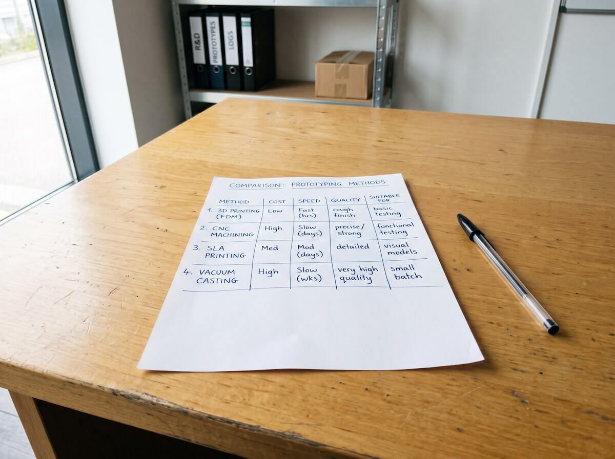

“How do I make a prototype” is really three different questions wearing one sentence. Are you checking whether a part fits inside an enclosure with everything else? Whether a mechanism actually moves the way it does in the CAD file? Whether the finish and feel will land with a customer? Or whether the design can even be manufactured at scale without a redesign? Each of those questions has a different right answer, and the method that answers one badly can still answer another perfectly well — which is exactly why “just 3D print it” or “just get a quote for a mold” are both incomplete advice on their own.
That’s the mistake worth avoiding before anything else: picking a prototyping method because it’s fast or familiar, rather than because it actually tests the thing that’s still in question. A gorgeous SLA print tells you nothing about whether a snap-fit will survive daily use. A CNC-machined block in the exact right resin tells you nothing about whether a complex geometry can even be molded. This guide walks through the four methods that cover almost every plastic prototyping need, in the order most projects actually move through them, and what each one can and can’t tell you along the way.
It’s worth saying upfront that none of these methods is a “better” or “worse” version of the others — they’re not competing on a single scale of quality. A $30 3D print and a $3,000 aluminum tool aren’t different tiers of the same thing; they’re answering different questions at different points in a project’s life, and using the expensive one to answer a question the cheap one could have answered just as well is its own kind of waste.
Start With What You’re Actually Testing
Before choosing a method, it’s worth naming the specific question this round of prototypes needs to answer, because the four categories below rarely overlap as much as people expect. A method that’s excellent at one can be actively misleading for another, which is exactly how teams end up “prototyping” a design flaw straight through to production without ever catching it.
- Fit — does this part sit correctly against the other components around it?
- Function — does a moving part, snap-fit, or mechanism actually work under real load and repeated use?
- Appearance — does the surface finish, color, and feel match what you’re planning to sell?
- Manufacturability — can this exact geometry actually be produced at volume, or does the design need to change first?
A single project often needs to answer all four at different points, which is exactly why most serious product development runs through more than one of the methods below rather than settling on a single “prototyping process.” The goal isn’t finding the one best method — it’s knowing which one to reach for at each stage.
Take a simple example: a hardware startup developing a clip-on accessory. Round one is purely about fit — does the clip geometry actually match the product it’s meant to attach to, and does it clear every button and port around it? That question gets answered fastest and cheapest with a 3D print, often within a day, and probably needs two or three quick iterations before the geometry is right. Round two shifts to function — does the clip mechanism actually flex and hold with enough force, cycle after cycle, without snapping? That’s where a 3D print starts lying to you, because printed plastic doesn’t flex or fatigue the way molded plastic does, and a CNC-machined sample in the real resin becomes the honest test. Only once both of those are settled does it make sense to ask the appearance and manufacturability questions that the later methods in this guide are built for.
3D Printing: The Fastest Way to Hold Something in Your Hand
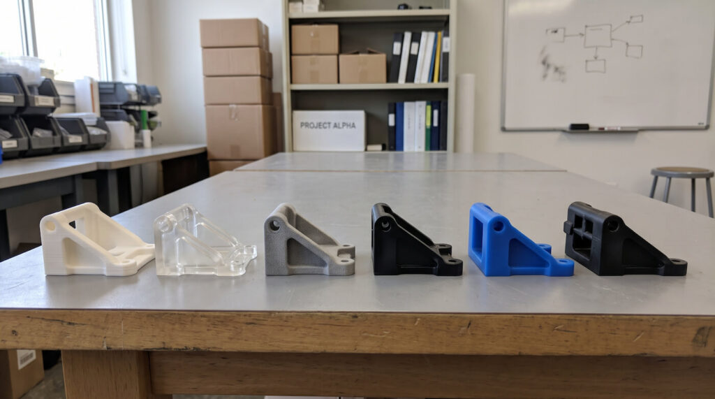
Nothing beats 3D printing for speed at the earliest stage. FDM printers extrude a plastic filament layer by layer and are the cheapest, fastest option for a rough geometry check — usually ready same-day or next-day, often for well under a hundred dollars a part, with visible layer lines and looser tolerances that are fine for confirming basic proportions but not for judging a finished surface. SLA (resin) printing swaps filament for a UV-cured liquid resin, giving a much smoother surface and finer detail, which matters when a prototype needs to look presentable in a pitch deck or an early customer conversation — the trade-off is a more brittle part that isn’t a great stand-in for a tough engineering resin. SLS (powder-based) printing sits between the two on finish quality but produces genuinely functional nylon parts without support structures, since unprinted powder holds everything in place during the build, which makes it useful for a first pass at moving or interlocking geometry that FDM and SLA both struggle to print cleanly — a hinge, a living clip, or nested parts that need to move against each other right out of the machine.
What 3D printing doesn’t do well, across all three variants, is tell you much about how a part will behave in its actual production material. Printed plastics — even ones marketed as similar to ABS or PP — have different layer-bonding characteristics than an injection molded part, and mechanical properties can vary meaningfully by print orientation in a way a molded part never will: a part that’s strong when loaded one direction can be noticeably weaker loaded the other way, purely because of how the layers were oriented on the print bed. A snap-fit that flexes fine on an SLA print can behave completely differently once it’s molded in the real resin. Our detailed comparison of injection molding and 3D printing goes deeper into where that gap shows up and when 3D printing stops being representative enough to trust.
Where 3D printing earns its place is early and often: checking whether a housing fits around existing electronics, showing a design to stakeholders before committing to tooling, or iterating through several geometry changes in the same week without paying for a new mold each time. It’s genuinely hard to overstate how much that iteration speed changes a project’s risk profile — catching a clearance problem on day two of a print cycle costs almost nothing, while catching the same problem after a mold is cut can mean weeks of delay and a real invoice for the fix. Our 3D printing prototyping service is usually the first stop for exactly that kind of early-stage, fast-iteration work.
CNC Machining: When the Prototype Needs to Behave Like Real Plastic
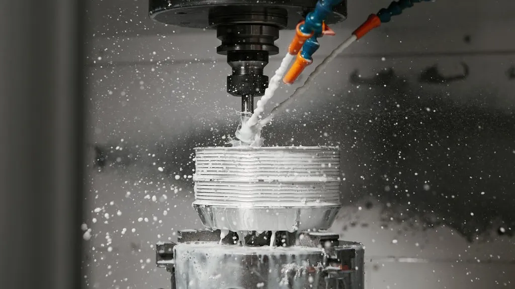
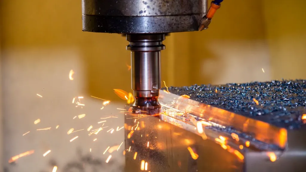
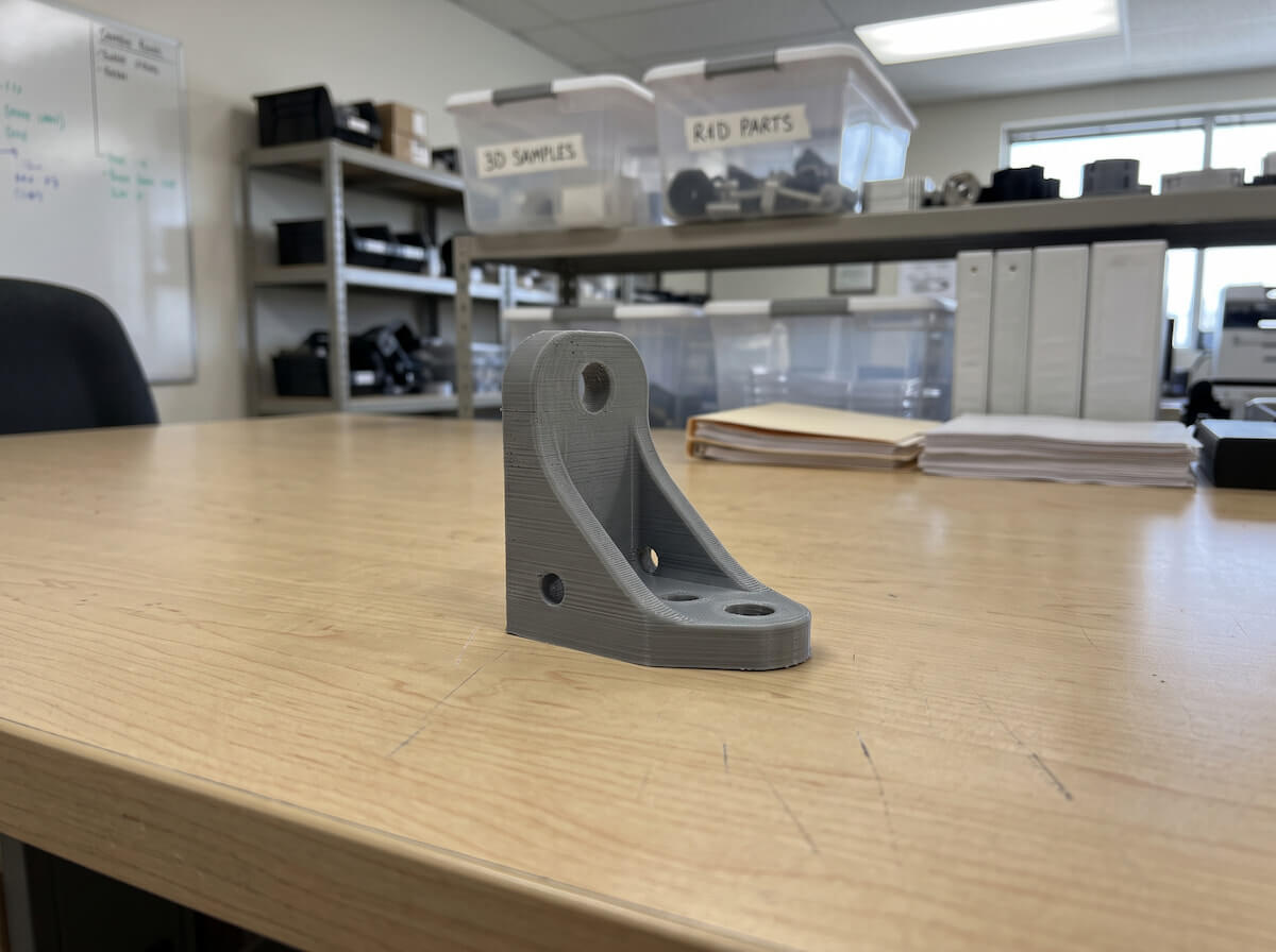
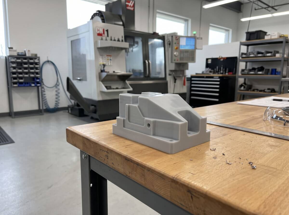
CNC machining cuts a prototype directly from a solid block of actual engineering plastic — real ABS, real polycarbonate, real nylon, real acetal — using a milling or turning process rather than building it up in layers. That single difference is what makes it the right choice once a project moves past “does this look roughly right” into “does this behave correctly.” A machined part carries the real mechanical properties, the real thermal behavior, and the real surface hardness of its material, because it is that material, not an approximation of it. It also holds tighter, more predictable tolerances than most 3D printing processes, which matters for anything that needs to mate precisely with another part — a bearing bore, a threaded boss, a sliding mechanism — and it’s often the fastest way to get a functional test part into an engineer’s hands in a material a lab test or a drop test will actually take seriously.
The trade-off is geometry and cost. CNC machining struggles with deep internal cavities, complex undercuts, and thin-walled enclosed shapes that a cutting tool simply can’t reach — geometries that print or mold without issue can be impossible or extremely expensive to machine, sometimes requiring the part to be split into pieces and bonded afterward, which introduces its own weak points. Cost also climbs with part complexity in a way 3D printing’s cost doesn’t, since more machining time, more tool changes, and more fixturing setups all add up quickly on an intricate design. It’s the right tool for a relatively simple geometry that needs to be tested in its true material — a functional test part, a fixture, a component that will see real mechanical stress before anyone commits to a mold.
This is also where design intent gets tested against manufacturing reality for the first time. A wall section that machines cleanly might still need adjustment before it can be molded, since machining and injection molding tolerate different geometry in different ways — a machined part has no need for draft angles or careful wall-thickness transitions the way a molded part does, so a design that machines perfectly can still turn out to have features that would sink, warp, or short-shot the moment it’s actually molded. Catching that gap here, on a single machined sample, is exactly the kind of check our CNC prototyping service is built to run early, before it becomes a mold modification later.
Vacuum Casting: Multiple Copies in Something Closer to Production Material
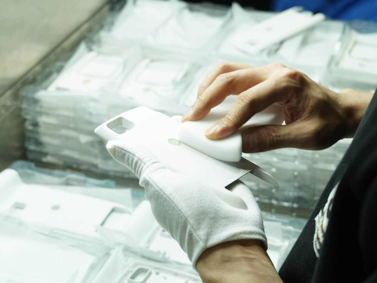
Once a design needs to exist as more than one identical copy — for user testing, a small pilot batch, or a trade show where several units need to look and feel finished — vacuum casting picks up where single-part methods leave off. A silicone mold gets built from a master pattern, usually a 3D printed or machined original, and a two-part polyurethane resin is poured in under vacuum to pull out air bubbles before it cures. The whole cycle from finished master pattern to a small batch of parts typically takes under two weeks, which is still fast compared to any steel-tooled option. The resins are formulated to simulate specific production plastics — ABS-like, PC-like, various rubber hardnesses — which gets a batch of parts much closer to the intended material’s look and feel than a 3D print can, right down to matching color and surface texture across the whole batch.
“Closer to” is doing real work in that sentence, though. Cast resin still isn’t the actual injection-grade thermoplastic, and the two behave differently under long-term stress, repeated flexing, and UV exposure — a distinction covered in more depth in our guide to moulding and casting materials. A silicone tool also has a limited life, good for roughly 20 to 25 parts before cavity detail starts degrading, which keeps this firmly in prototype and small-batch territory rather than production.
Vacuum casting is the right call specifically when the number of prototypes needed is bigger than “a few for the team to look at” but nowhere near production volume — a batch for a focus group, a crowdfunding campaign’s demo units, or a run of samples to send to potential retail buyers before a single dollar goes toward steel tooling. It’s also a practical way to test color and gradient options across a small batch before locking in a final palette, since a silicone mold can run different colored resin pours without any tooling change between batches. Our vacuum casting service covers this exact stage.
Rapid Tooling: The Last Prototype Before the Real Mold
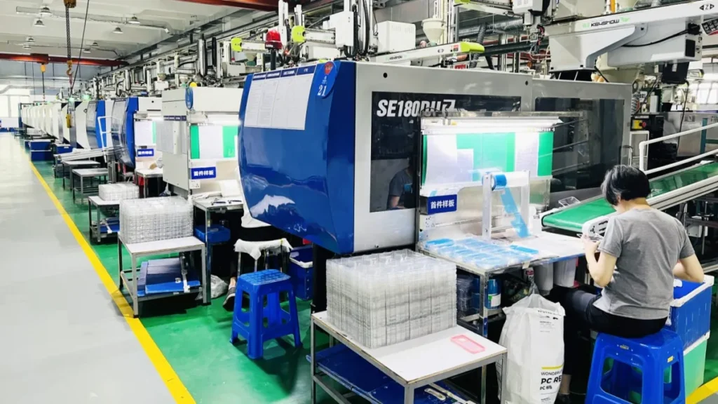
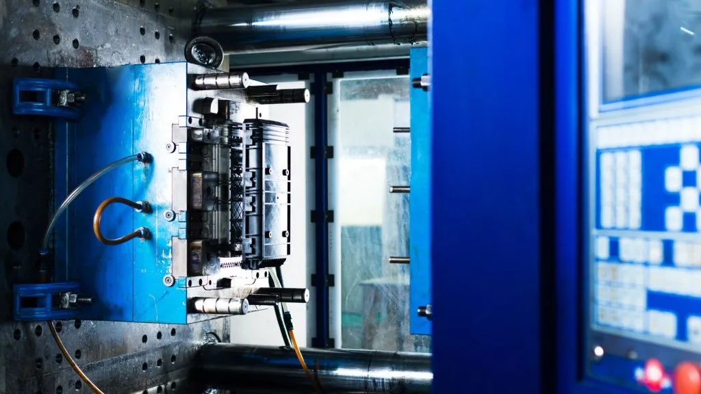
At some point, the only way to really know whether a design works is to injection mold it — in the actual production resin, through the actual process it will ship in. Rapid tooling makes that possible without committing to a full production mold. An aluminum tool, rather than hardened steel, gets machined for the cavity and core, cutting both lead time and cost dramatically compared to a production-grade mold — often ready in about a week to ten days rather than the four-to-six-plus weeks a hardened steel tool typically takes, since aluminum cuts far faster than tool steel and needs less finishing work before it’s ready to run.
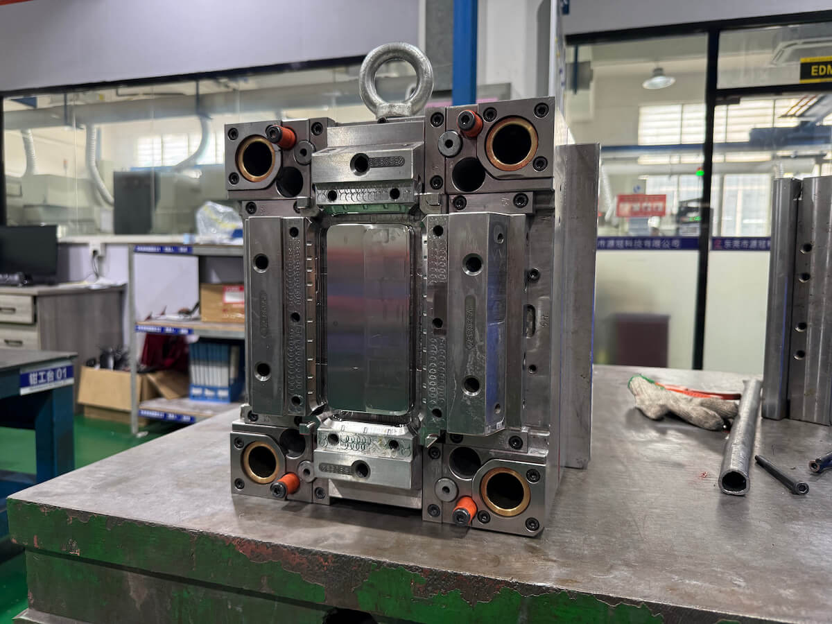
The trade-off is mold life, not part quality — parts that come off an aluminum tool are genuine injection molded parts, in the real resin, through the real process, not a stand-in or approximation of one. Protolabs’ own tooling data puts aluminum prototype tooling at a guaranteed minimum of around 2,000 shots, often running well past 10,000 depending on the part and resin — more than enough to validate a design, run a pilot batch, or even cover an entire limited production run without ever cutting a hardened steel tool. A single-cavity aluminum tool can also usually be modified relatively cheaply if a design tweak is needed after the first round of samples, since aluminum machines quickly for a rework the same way it does for the original cut — a much smaller correction than discovering the same issue on a multi-cavity production mold, where the same fix has to be repeated across every cavity and the machine time adds up fast.
This is the stage that actually answers the manufacturability question from the very first section of this guide — not “does this look right” or “does this feel right,” but “can this be built, repeatably, at the tolerance the drawing calls for.” Our rapid tooling program is built around exactly this handoff: validate on aluminum first, then move to production steel once the design is genuinely locked and volume justifies the bigger tooling investment.
Matching the Method to the Stage
Laid out side by side, the four methods sort themselves cleanly by what they’re actually good for.
| Method | Best For | Typical Lead Time | Material Accuracy |
|---|---|---|---|
| 3D Printing | Fit checks, fast iteration, early-stage review | Same day–3 days | Low |
| CNC Machining | Functional testing in real material, simple geometry | 3–7 days | High |
| Vacuum Casting | Small batches, appearance and cosmetic testing | 5–10 days | Medium |
| Rapid Tooling | Manufacturability validation, pilot runs | 7–10 days | Exact |
Many projects move through this table roughly left to right — a 3D print to check the geometry, a CNC part to confirm a snap-fit actually holds, a small cast batch for early reviewers, then a rapid tool to prove the design out in the real process before committing to production steel. Skipping straight to the last column without the earlier checks is how an expensive tooling change gets discovered after the mold is already cut, rather than a week earlier on a $50 machined part.
It’s also worth resisting the opposite mistake: running every design through all four stages out of habit, even when a part is simple and low-risk enough that a single 3D print and a rapid tool would answer everything that actually needs answering. The table above is a map, not a checklist — the point is picking the method that matches the specific question still open on a given part, not working through every box for the sake of thoroughness. A simple bracket with no moving parts and a forgiving tolerance might reasonably skip straight from a 3D print to a rapid tool; a complex mechanism with tight tolerances and repeated-use requirements might genuinely need all four before anyone signs off on production tooling.
The projects that waste the least time and money tend to share one habit: they treat each prototype as a specific test with a specific pass-or-fail question attached, rather than a generic “let’s see how it looks” step. Write down what this round needs to prove before choosing how to build it, and the right method on this page usually becomes obvious.