

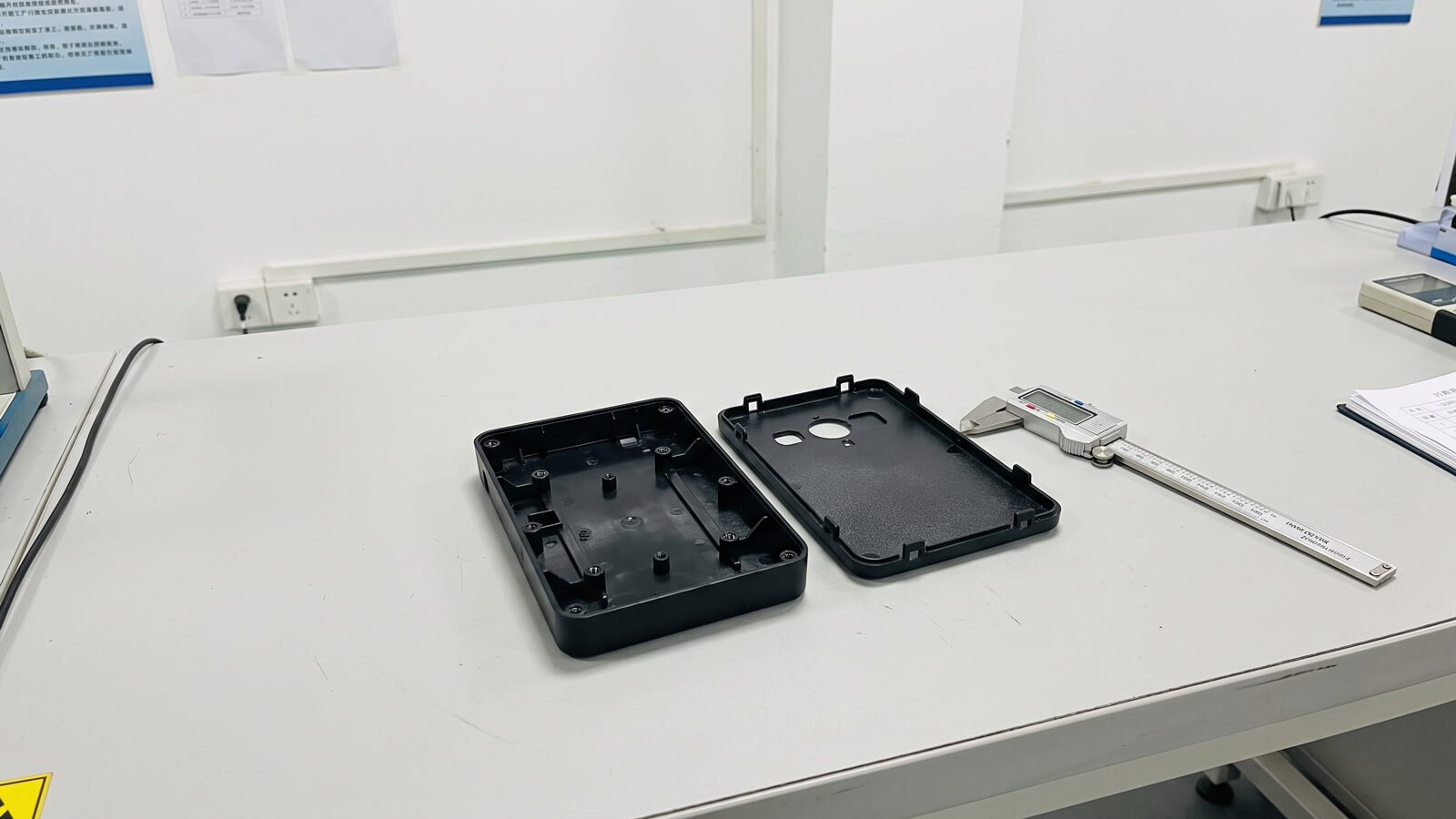
A surprising number of RFQs reach our engineering desk with a single drawing note: “General tolerance ±0.05 mm.” It is an understandable habit. Anyone who has ordered CNC aluminum parts knows that number is routine. But plastic does not behave like aluminum, and applying the same blanket limit to a molded part usually means one of two outcomes: a quote that comes back much higher than expected, or a supplier who quietly accepts the note and then argues about it at first-article inspection.
This guide is written from the factory side. It covers what tolerances are realistic for molded parts, how they change by material, where to spend tight limits and where not to, and how to write a drawing so nobody has to guess.
Tool Tolerance vs. Part Tolerance: Where the Variation Comes From
Two different numbers get mixed up in most tolerance conversations. The first is how accurately the mold steel is machined. At YG, mold tolerance is routinely held to ±0.01 mm on critical cavity and core features. The second is how accurately the plastic part reproduces that steel, and this is where things drift. Shrinkage, packing pressure, cooling rate, ejection, and moisture uptake all move the final dimension after the mold has done its job.
Even large digital manufacturers treat sub-0.1 mm as a special request. One major network publishes a standard mold machining tolerance of ±0.125 mm after shrinkage adjustment and treats anything tighter as best effort, with possible extra charges if the tool must be altered after first-article inspection (Source: Protolabs Network manufacturing standards, January 2024). The lesson for a buyer is simple: a tight limit is a negotiated item, not a default.
There is also a formal framework. ISO 20457 (second edition published 2026) is the plastics-specific standard for molded-part tolerances and acceptance conditions. It covers general tolerances, direct tolerances, and the limits of technical manufacturability, and it exists because tolerance approaches built for metal do not transfer directly to plastic. Referencing it on a drawing gives both sides a shared baseline instead of an opinion.
One more distinction matters in practice. Dimensions formed entirely within one mold half (a cavity depth, a boss diameter) hold tighter than dimensions that depend on the mold closing or on a moving slide, such as wall thickness across the parting line or a feature formed by a lifter. When we review a drawing, we sort every toleranced dimension into one of these two groups before quoting.
Achievable Tolerances by Material
Material choice sets the floor. Shrinkage varies from roughly 0.3% in glass-filled engineering grades to well over 2% in semi-crystalline commodity resins, and the more a material shrinks, the more room there is for that number to vary from lot to lot. The bars below show typical shrinkage ranges. For selection beyond tolerance (strength, heat, chemical exposure), see our injection molding material selection guide.
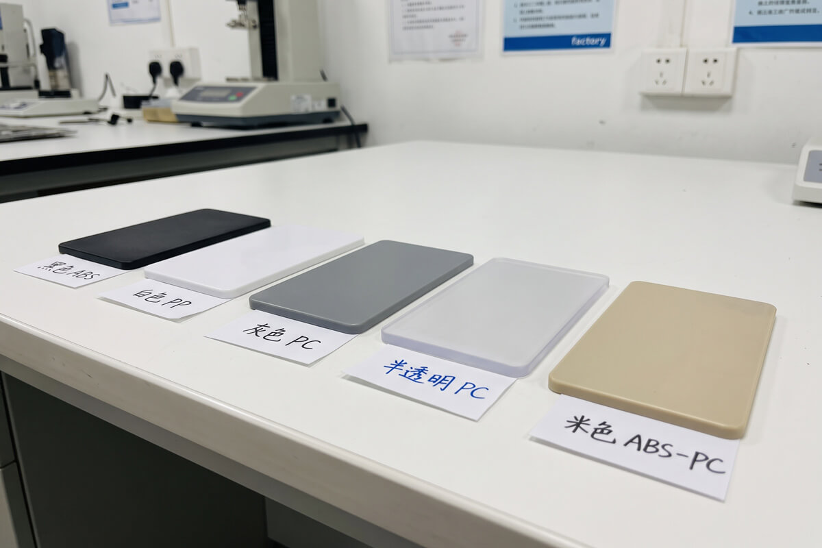
Translating that into numbers we actually quote against, here are working ranges for features up to roughly 50 mm, formed within one mold half, at production volumes of 1,000 pieces or more. They are planning figures, not guarantees; geometry can move them in either direction.
| Material group | Commercial tolerance | Fine tolerance (agreed in advance) |
|---|---|---|
| ABS, PC, PC/ABS | ±0.10 mm | ±0.05 mm |
| PPS GF40, PA GF30 | ±0.08 mm | ±0.03 to ±0.05 mm |
| POM, unfilled PA | ±0.15 mm | ±0.08 mm |
| PP, HDPE | ±0.20 mm | ±0.10 mm |
| TPU, TPE | ±0.25 mm | ±0.15 mm (flexible, hard to measure) |
Add allowance as the part grows. Resin tolerance scales with length, which is why a published resin figure is usually expressed per unit of length (the Protolabs guideline, for example, treats ±0.002 in./in. as a floor, see their design guidelines). A 120 mm dimension cannot carry the same absolute limit as a 12 mm one.
A Tolerance Budget: Where Tight Limits Earn Their Cost
Good drawings are selective. We ask customers to sort features into three tiers so the tight limits land only where function depends on them. The wall thickness, draft, and rib rules that support all three tiers are covered in our guide on how to design for injection molding, so we won’t repeat them here.
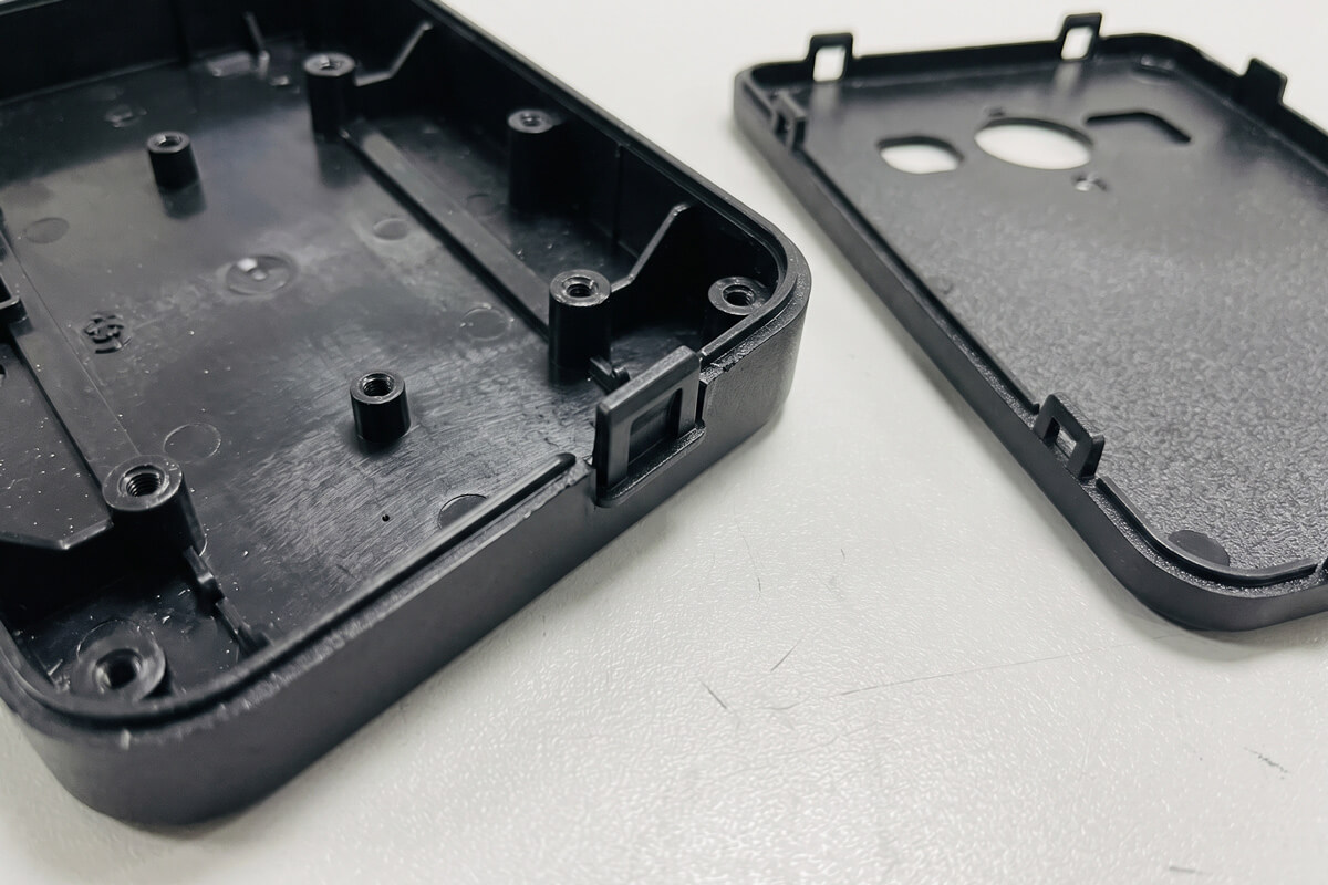
In my experience, a drawing with five or six well-chosen Tier 1 dimensions is cheaper to build and easier to inspect than one with forty equally tight numbers, and it ships with far fewer disputes. If your product sits in the $30-plus accessory range, where fit and feel are part of what the buyer is paying for, those few dimensions deserve real attention. For a concrete example of how this plays out on consumer accessories, see how we approach a phone case manufacturing project.
Worked Stack-Up: A Two-Piece Enclosure Gap
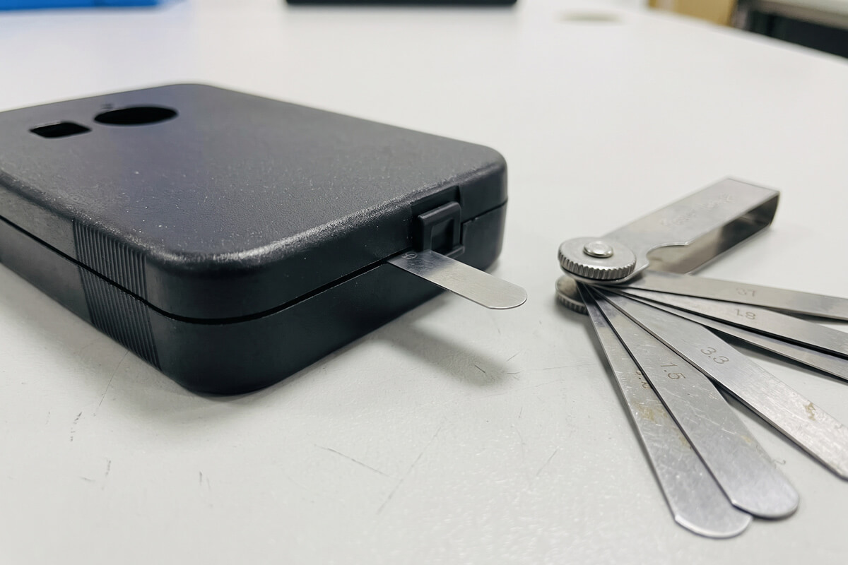
Individual tolerances rarely cause trouble. Stacks do. Take a protective case with a base and a lid, designed for a 0.15 mm perimeter gap when closed. Three contributors affect that gap:
- Base lip dimension: ±0.08 mm
- Lid lip dimension: ±0.08 mm
- Warpage at the corners: ±0.05 mm
- Worst-case sum: ±0.21 mm
- Root-sum-square (RSS): ±0.12 mm
- Target gap: 0.15 mm
Worst-case stacking says the gap can swing past the design value, with the lid either sitting proud or binding. RSS, which assumes the variations are independent and the process is stable, lands inside the target. For a run of several thousand pieces, RSS is the more realistic model, but only if the process is under control. That is why we pair a stack-up with a capability target on the critical dimensions rather than relying on the average.
The practical fix is rarely “tighten everything.” It is usually to redesign the joint with a tongue-and-groove or a stepped lip that tolerates ±0.2 mm without looking sloppy, then hold one dimension tightly and let the other float.
What Tight Tolerances Add to Cost and Lead Time
Every step from commercial to fine tolerance adds work somewhere in the chain. The main drivers we see:
- Mold build: steel is cut conservatively (“steel-safe”) and then adjusted after the first trial to hit the dimension. Tight limits mean more adjustment rounds.
- Tool steel and cavity count: hardened, stable steel and fewer cavities keep cavity-to-cavity variation down, which raises tooling cost per part.
- Cycle time: longer packing and cooling improve repeatability but slow every shot.
- Inspection: CMM or optical measurement takes longer than a go/no-go gauge and adds up across lots.
- Scrap risk: a narrow process window means more parts rejected for small drift.
Our breakdown of injection mold cost shows how these drivers sit alongside size and complexity. If you want to see real shrinkage on your geometry before cutting the production tool, a short-run rapid tooling mold gives you measured data to build the final steel around.
How to Write Tolerances So Nobody Has to Guess
- Flag critical-to-quality (CTQ) dimensions explicitly; leave the rest to a stated general tolerance.
- Reference a recognized general tolerance standard such as ISO 20457 and agree on the group with your supplier.
- Define the datum scheme once. Use a surface profile tolerance where a feature’s shape matters more than its size.
- State inspection conditions. Plastic parts keep moving after ejection, so measure after conditioning (commonly 24 to 48 hours at room temperature) and say so on the drawing.
- Exclude gate vestige, ejector marks, and parting-line witness areas from measurement.
- Agree on the measurement method and capability target (Cpk) for CTQ items before tooling starts.
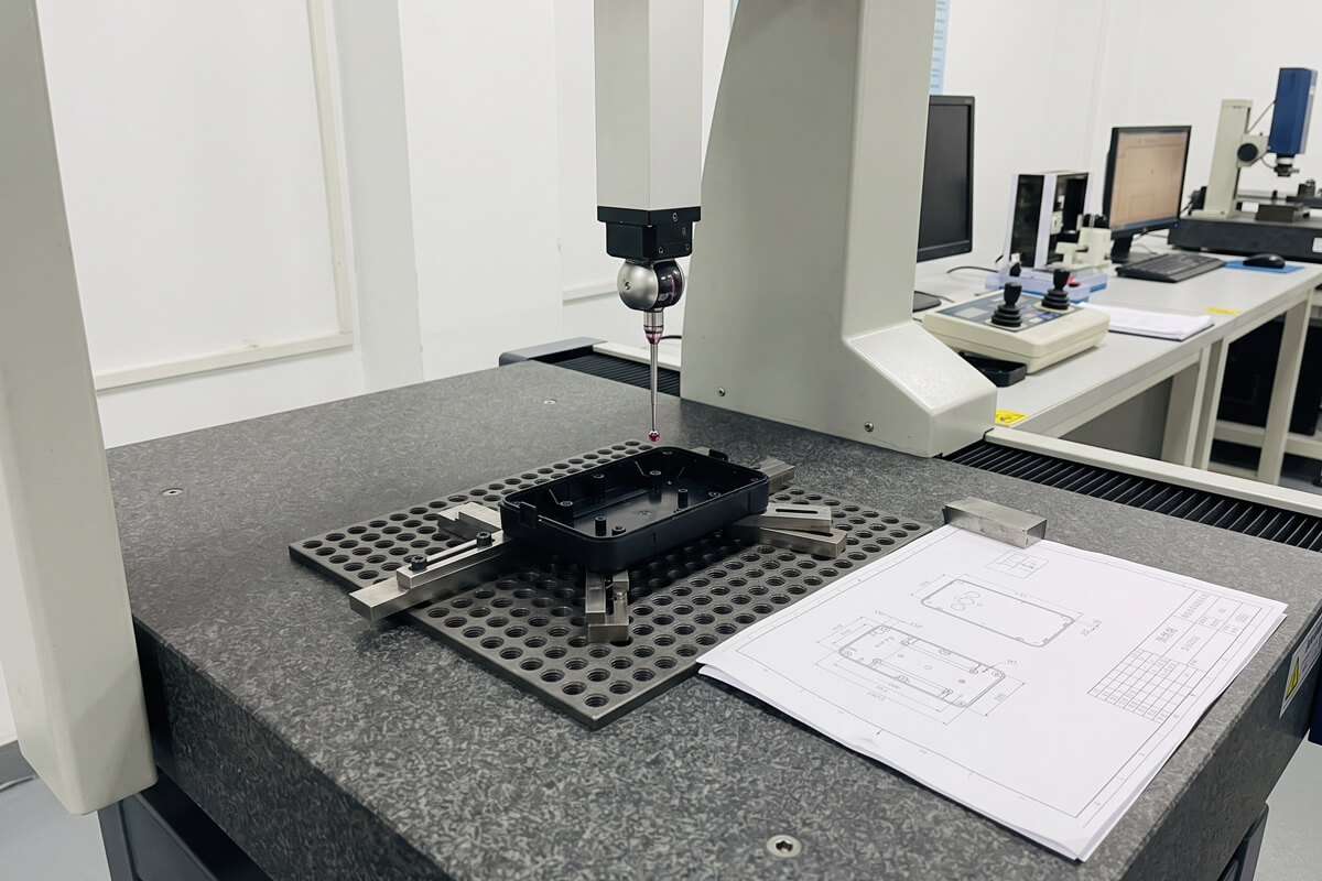
Our quality assurance process works from this kind of agreed inspection plan. It is also how we handle the occasional nonconformance: trace the cause, then agree on a fix, rather than defaulting to a blanket return.
Frequently Asked Questions
What is the standard tolerance for injection molding?
Most commercial injection-molded features hold between ±0.10 mm and ±0.25 mm for dimensions under about 50 mm, depending on material. Common planning rules:
- Amorphous resins (ABS, PC): around ±0.10 mm.
- Semi-crystalline resins (PP, HDPE): around ±0.20 mm.
- Larger dimensions need proportionally more allowance.
How tight can injection molding tolerances go?
Mold steel can be machined to ±0.01 mm, but molded parts typically hold ±0.03 to ±0.05 mm at best, and only on small features in stable, low-shrinkage resins such as glass-filled PPS or nylon. Tighter than that usually needs a secondary machining step.
What does ISO 20457 cover?
ISO 20457 is the international standard for tolerances and acceptance conditions of plastic molded parts. It covers:
- General tolerances for features without a specific callout.
- Direct tolerances for functional features.
- Limits of what the process can technically achieve.
It applies to non-porous parts made by processes including injection molding and compression molding.
How does shrinkage affect injection molding tolerances?
Shrinkage changes every dimension after the part leaves the mold, so higher or less consistent shrinkage means wider tolerances. Key points:
- Semi-crystalline materials shrink more than amorphous ones.
- Glass fiber lowers shrinkage but makes it direction-dependent.
- Thick sections shrink more than thin walls.
- The mold is cut with a shrinkage allowance based on the chosen resin.
Why do molded parts go out of tolerance after production starts?
The most common causes are process drift, uneven cooling, and warpage. To prevent it:
- Keep wall thickness uniform.
- Lock the process window at first-article approval.
- Control resin lot and drying.
- Monitor CTQ dimensions with agreed sampling.
Our guide to plastic molding defects and remedies covers warpage and sink in more detail.
Does part size change the tolerance I should specify?
Yes. Tolerance grows with length because shrinkage is proportional to size. A 100 mm dimension typically needs two to four times the absolute allowance of a 10 mm feature in the same material.