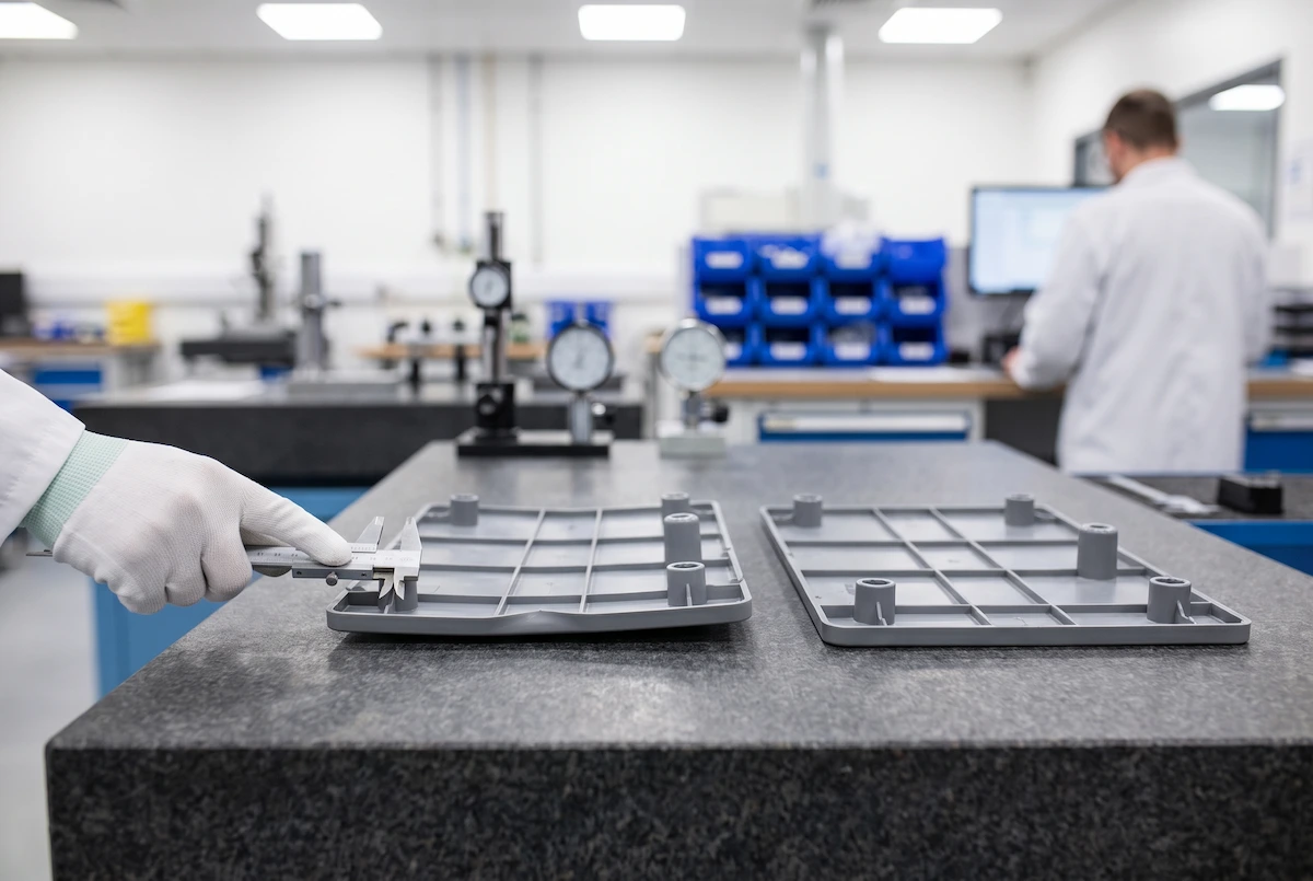

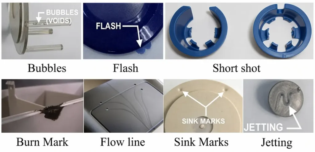
A T1 sample tray almost never comes back perfect. There’s usually a sink mark near a rib, a faint line where two flow fronts met, maybe a corner that’s lifted a fraction of a millimeter off the surface plate. The question that actually matters at that point isn’t “what’s this defect called” — most process engineers can name it on sight. It’s what happens next: does this get solved by turning a dial on the machine, or does someone need to put steel back in the mold? Get that call wrong and you either burn weeks chasing a fix the process was never going to deliver, or you spend on tooling changes a parameter adjustment would have solved for free.
This guide is built around that decision, plus the two others that come right after it: how to tell a defect that’s genuinely disqualifying from one that’s just cosmetic, and how to keep a fix from quietly failing the moment production switches to a new resin lot.
Process Tuning or Mold Modification? How to Tell Which One Actually Fixes It
The honest answer is that you can’t tell from looking at the defect alone — you have to test the process window and see how it behaves. That’s the core idea behind Scientific Molding: instead of nudging one setting at a time and hoping, you systematically map how the defect responds across a safe range of melt temperature, injection speed, and pack pressure, and see whether an acceptable combination actually exists.
The “no” branch is the one buyers dread, mostly because they’ve watched a shop keep tuning a process that was never going to get there — burning schedule while the actual cause, usually an undersized gate, a starved vent, or an uneven wall section, sits untouched. A reliable supplier will show you the process window study itself: the range of settings tried, where the defect improved, and where it hit a wall the process alone can’t cross. If the window closes before the defect clears — for instance, filling the part completely only above a melt temperature that starts degrading the resin — that’s the proof a design or mold change is genuinely needed, not just a stalling tactic.
Knowing which side of that line you’re on also changes the conversation about cost and timeline. A process fix costs almost nothing and can be locked in the same day. A mold fix means new steel, which is worth budgeting for honestly — our breakdown of what actually drives mold cost covers what a gate resize, added venting, or a cooling-line change typically adds to a project, so it’s not a surprise line item mid-production.
Critical, Major, or Minor? Where AQL Grading Actually Draws the Line
Not every defect is a reason to reject a batch, and not every defect is safe to wave through either — the disagreement usually happens because buyer and supplier never agreed on where the line sits before parts started shipping. The standard way to remove that ambiguity is AQL (Acceptable Quality Level) sampling, typically run against ANSI/ASQ Z1.4 or ISO 2859-1 tables, with defects sorted into three severity classes before a single part is inspected.
The classification only means something if it’s backed by a real test, not a judgment call on the inspection bench. A suspected weak weld line gets confirmed with a pull or impact test compared against a known-good baseline, not by eyeballing how visible the line looks. A suspected internal void gets confirmed with an X-ray, CT scan, or a destructive section cut, since voids in thick sections are frequently invisible from the surface entirely. Setting this criteria — and the accept/reject sample sizes that go with it — before production starts is what turns a shipping decision from an argument into a checklist. Our guide to defect grading and ROI goes deeper on building that framework and weighing rework cost against scrap cost; this section is focused specifically on the AQL sampling mechanics and the tests that back up a critical-versus-cosmetic call.
Stopping a Defect From Coming Back on the Next Resin Lot
A fix that only works for one batch of resin isn’t really a fix — it’s a coincidence waiting to run out. This happens constantly: T1 samples pass clean, then three months later a new resin lot with slightly different viscosity hits the floor and the exact same sink mark or short shot reappears, at the same “proven” settings. The settings were never the real fix; they just happened to sit inside a very narrow window that the first lot tolerated.
Design of Experiments (DOE) is how professional molders avoid that trap. Rather than finding one golden setting, DOE structures trials across a grid of parameter combinations to map which factors actually drive the defect and how much margin exists around each one — the difference between a setting that works and a process window robust enough to absorb normal lot-to-lot material variation.
| Low Pack Pressure | High Pack Pressure | |
| Low Melt Temp | Short shot risk | Workable window |
| High Melt Temp | Sink mark risk | Flash risk |
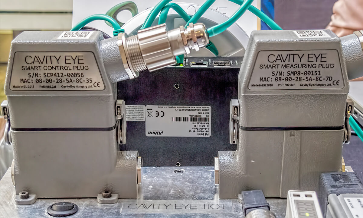
Once a real window is mapped rather than a single point, the second half of the fix is monitoring for drift inside that window in production. Cavity pressure sensors embedded near the end of fill give a per-shot reading of what’s actually happening inside the mold — a signal that doesn’t drift the way ambient temperature or barrel readings can. As one process engineering resource on pressure loss monitoring puts it, a pressure-loss baseline set during tool qualification gives a shop something concrete to compare future shots against, so a shift in material, mold condition, or press performance shows up as a measurable alarm rather than a mystery defect three months into production.
Frequently Asked Questions
What are the most common plastic injection molding defects and their causes?
The defects that show up most often on a first sample tray, and their typical root cause, are:
- Sink marks — insufficient pack pressure or pack time behind a thick section
- Warping — uneven cooling between mold halves or uneven wall thickness
- Flash — worn parting line, insufficient clamp tonnage, or excess injection pressure
- Short shots — undersized gate, low melt temperature, or blocked venting
- Weld lines — two flow fronts meeting head-on before fully fusing
- Silver streaks — moisture, trapped air, or thermal degradation in the melt
- Burn marks — trapped air compressing and scorching at the last point to fill
- Voids — thick sections cooling unevenly and shrinking internally
How do you fix sink marks without changing the part design?
With the design frozen, sink marks are addressed entirely through process settings rather than wall thickness or rib geometry.
- Increase pack (holding) pressure so more material is pushed in as the part shrinks
- Extend pack time to keep feeding the gate before it freezes off
- Lower melt temperature slightly to reduce overall shrinkage
- Increase gate size if any tooling change is allowed, since a larger gate stays open longer for packing
- Slow cooling locally near the sink-prone area so the surface doesn’t skin over before packing finishes
Why do plastic parts warp after being ejected, and how can warpage be prevented?
Warping happens when different areas of a part cool and shrink at different rates, so the part bends as it releases internal stress after ejection. Common causes include a temperature difference between the core and cavity sides of the mold, uneven wall thickness across the part, and insufficient pack pressure leaving some regions under-supported. Prevention usually means balancing mold temperature between both halves, keeping wall sections as uniform as possible — see our DFM guide for wall thickness guidelines — and holding parts in a cooling fixture immediately after ejection if the geometry is especially prone to it.
What is the difference between a weld line and a meld line in injection molding?
A weld line forms where two flow fronts meet head-on, moving directly toward each other — the fronts have cooled slightly by the time they touch, so they fuse weakly and the resulting line is a genuine strength concern. A meld line forms where two flow fronts merge moving roughly parallel to each other, which fuses far more completely and rarely raises the same strength concern. If a weld line lands on a load-bearing feature, the usual fix is repositioning the gate or adding a flow leader so the two fronts meet somewhere off the stressed area instead.
How does inadequate mold venting cause both short shots and burn marks (dieseling)?
Both trace back to the same trapped gas that a vent failed to release in time. If the trapped air simply blocks the melt from reaching the last corner of the cavity, the result is a short shot. If the melt keeps pushing and compresses that trapped air hard enough, the air can heat sharply enough to scorch the surrounding plastic — a phenomenon called dieseling — leaving a burn mark at exactly the point the cavity was hardest to fill. We cover the venting mechanism, typical vent depths, and how to diagnose it against other gas-related defects in full detail in our dedicated guide to venting and silver streaks.
Why does flash (burrs) occur in injection molding, and how do you eliminate it?
Flash happens when molten plastic escapes past the parting line instead of staying fully contained in the cavity, and it usually comes down to one of three causes.
- Clamping force too low for the part’s projected area, letting injection pressure push the mold halves apart slightly
- A worn or damaged parting line surface that no longer seals tightly — this needs the mold reworked, not a process change
- Injection pressure or speed set higher than the part and mold actually need
Confirming which one is at fault starts with checking clamp tonnage against the part’s projected area, then inspecting the parting line surface itself — our guide to mold construction covers how parting-line fit is machined and maintained to prevent this from the start.