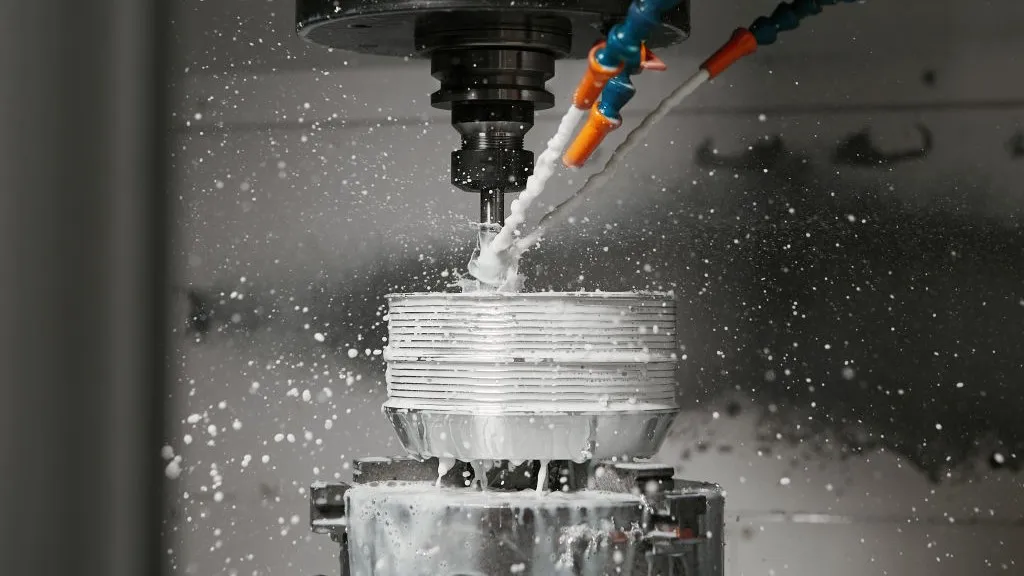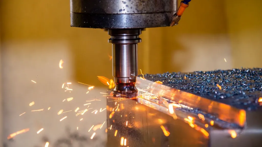

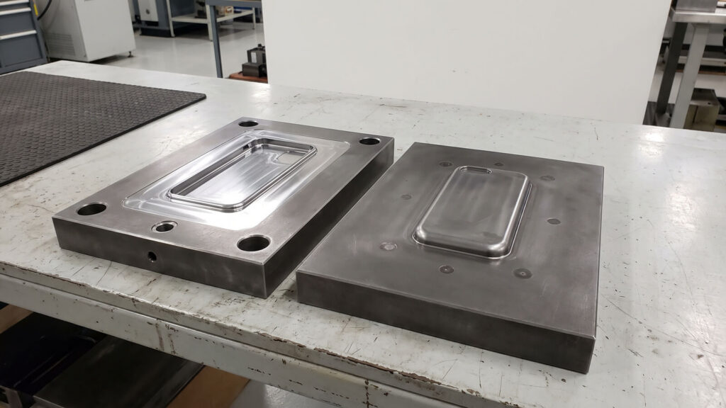
Anyone who has lived through a failed T1 trial knows how it plays out. The first shots show a short fill, a sink mark or a flash line. The mold goes back to the toolroom, someone welds the cavity, the texture is redone, and a gap of several weeks opens in the launch schedule. Worse, welded steel never wears like virgin steel, so the tool carries that repair for life.
Here is how I define “perfect” when I walk a customer through a tooling plan. It is not a mold that never needs adjustment. It is a mold whose adjustments were designed to be cheap (removing steel, not adding it), whose steel and parting line were fixed on paper before the first cut, and whose build can be proven with documents rather than promises. The rest of this article follows that logic.
01Locking Steel, Cooling, and Steel-Safe Allowances at the CAD Stage
Re-machining after T1 happens for a small number of predictable reasons: a dimension that shrank differently than the datasheet suggested, a hot spot nobody saw coming, a vent in the wrong place, or steel that is too soft for the resin. Each of these can be reduced on the screen, where a change costs hours instead of weeks. The sequence below is the one we follow.
Steel-safe design: leave metal where you cannot yet know
Resin datasheets give shrinkage as a range, and the real number depends on wall thickness, gate location and packing. So on features where fit matters (bosses, mating lips, shut-offs, core pins) we machine the steel slightly on the safe side, typically a few hundredths of a millimeter to around 0.1 mm depending on the feature, then trim after T1 measurements. Removing steel is clean. Adding it means welding, which creates a heat-affected zone, risks cracking, can leave a texture or gloss mismatch, and shortens the life of that spot.
Conformal cooling: use it where drilled lines cannot reach
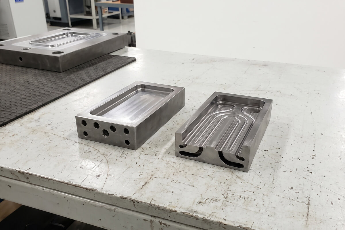
Conformal cooling means channels that follow the part shape, usually made as 3D-printed steel inserts placed into the hardest spots of an otherwise conventional mold. It earns its cost on deep cores, tall thin bosses and thick sections that trap heat, because even temperature reduces warpage and shortens the cooling phase, which is the biggest slice of the cycle. It is not free: printed channels cannot be reamed out, so they need filtered coolant and a flushing routine. For a simple accessory lid or case, well-placed baffles and bubblers usually do the job at lower cost.
What “perfect at T1” can honestly promise
No supplier can guarantee zero adjustment on every program. What good CAD-stage work can promise is that T1 parts land inside the critical tolerances, that the corrections still needed are small and made by cutting steel, and that none of them involve welding a cavity. Our step-by-step mold making guide covers the build itself. For a brand-new geometry, a short-run rapid tooling mold can also confirm shrinkage and fit before you commit to hardened production steel.
02Precision Matching Metrics for Zero Flash and Clean Parting Lines
Flash is a gap problem. As a rule of thumb, medium-viscosity resins start to flash at a gap of roughly 0.02 mm, and thin-flowing grades such as nylon can flash below 0.01 mm. A parting line widens over hundreds of thousands of shots through wear, mold deflection under clamp force, and hobbing of soft steel. So the question for a buyer is not “is the mold precise?” but “what was measured, and what was the target?” These are the targets I would write into a mold spec.
| Metric | Target to write into the spec | Evidence to request |
|---|---|---|
| Parting surface contact | Even bluing transfer across the full shut-off band, no rocking | Photos of the bluing check under press load |
| Step between mold halves | Under 0.02 mm at the parting line | Optical or CMM alignment record |
| Shut-off fit (core to cavity, slides) | Line-to-line fit in the 0.005 to 0.01 mm range | Fitting record per shut-off |
| Shut-off angle on sliding faces | 3 degrees or more, to avoid galling | Approved 3D mold design |
| Cavity surface vs. CAD | Within the agreed mold tolerance on critical surfaces | Blue-light scan or CMM deviation map |
| Press tonnage margin | Clamp force above projected area times cavity pressure, with margin | Flash trial at T1 |
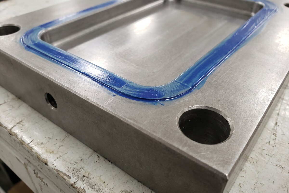
Two supporting practices matter over the long run. First, hardened parting surfaces and enough support pillars behind large cavities limit deflection under clamp force. Second, the precision of the cut itself counts: our article on precision wire EDM and flash elimination explains how micro-tolerance machining closes gaps that milling alone leaves open. Whichever supplier you use, ask for measurement records, not equipment lists. Our own inspection routines are outlined on the quality assurance page.
03SPI Class 101 and Steel Documentation: Protecting Your CapEx
When you pay five or six figures for a mold, the quiet risk is substitution: softer steel than quoted, or a class label that does not match the build. The SPI mold-building standards exist to make that checkable. They rank molds by rated life and define what each class must contain.
Steel is where most of the money and most of the confusion sit, so here is the practical comparison.
- Machined at final hardness, so no heat-treat distortion
- Faster and cheaper to build and modify
- Best for non-abrasive resins and moderate volumes
- Resists wear from glass-filled resins and high shot counts
- S136 is corrosion-resistant and polishes to a mirror, suiting clear parts
- Needs heat treatment, so allowances matter more
The documents below turn “trust us” into something you can verify. Ask for them before the deposit, not after the trial.
- Steel mill certificates showing grade and heat or lot number
- Heat-treatment report with measured hardness for each cavity and core
- Steel type and hardness marked on every detail, as the SPI general specification asks
- Your signed-off 3D mold design and bill of materials
- T1 trial report, first-article measurements and a spare-parts list
- Written confirmation that the tool is yours (at YG, mold ownership is 100% yours after full payment, under an NDA signed up front)
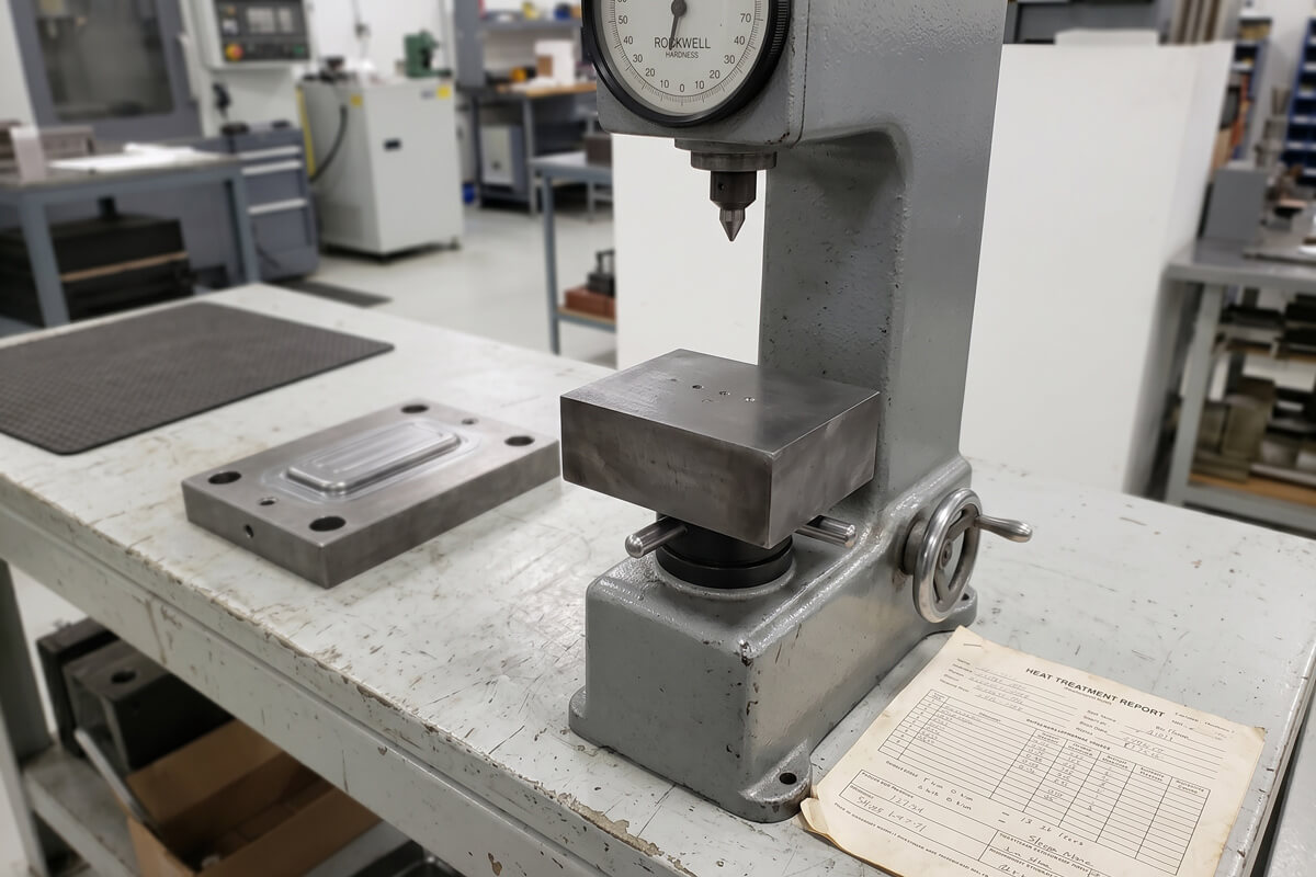
One honest point about class selection. Class 101 is the most expensive construction, and many programs do not need it. A launch with a 1,000-piece minimum order rarely heads toward a million shots. Our standard tool life is 300,000 shots, extendable to 500,000 with hardened cavity steel, which covers most accessory programs. If your volume plan truly points past that, tell us at the quoting stage so we can scope steel, guided ejection and cooling to that target and tell you plainly what it adds. Our breakdown of injection mold cost and the comparison of soft tooling vs. hard tooling will help you size that decision.
Frequently Asked Questions
What defines a “perfect” injection mold in precision manufacturing?
A perfect injection mold makes parts that meet the drawing from T1, holds them for its rated shot life, and ships with proof of how it was built. Use this acceptance checklist:
- Critical dimensions within the agreed tolerance, confirmed by a first-article report
- Surface finish to a stated SPI, VDI or texture standard, consistent across cavities
- Balanced cooling with no hot spots
- Vents clear: no burn marks, no flash
- Tight parting line and shut-offs
- Steel grade, hardness and SPI class documented
- Maintenance plan and spare-parts list delivered
How does Moldflow simulation help achieve a perfect mold steel layout before machining?
Moldflow simulation predicts fill pattern, pressure, weld lines, air traps and warpage trends before steel is cut, but it does not predict them with 100% accuracy. What it is good for:
- Choosing gate position and number
- Placing vents at predicted air traps
- Laying out cooling lines around hot spots
- Estimating warpage so compensation can be built in
Accuracy depends on material data and process assumptions, so treat results as risk reduction and confirm at T1.
What steel hardness (HRC level) is required for high-precision, long-life injection molds?
Hardened steels at about 48 to 52 HRC (S136, H13) suit high-precision, long-life molds, while pre-hardened P20 or 718H at about 28 to 34 HRC suits shorter, non-abrasive runs. Glass-filled resins and clear optical parts are the usual reasons to step up to fully hardened steel. The comparison above shows the trade-offs, and our material selection guide covers the resin side.
Why is mold venting critical for a flawless surface finish without burns?
Vents let trapped air and gas escape the cavity; without them, compressed air burns the resin and leaves short shots and weak weld lines. Depth is the critical dimension, because flash occurs only when a vent is too deep, not too wide (Source: Plastics Technology, “Back to Basics on Mold Venting,” updated October 2023). Typical recommended depths:
- Crystalline, free-flowing resins (nylon, PE, PP): about 0.013 to 0.025 mm
- Viscous amorphous resins (PC, TPU): about 0.025 to 0.076 mm
- Land length at least about 0.76 mm, then a deeper relief channel
- Polished vents, kept as wide as practical
See our guide to plastic molding defects and remedies for burn mark troubleshooting.
How do high-speed CNC and mirror EDM improve mold cavity perfection?
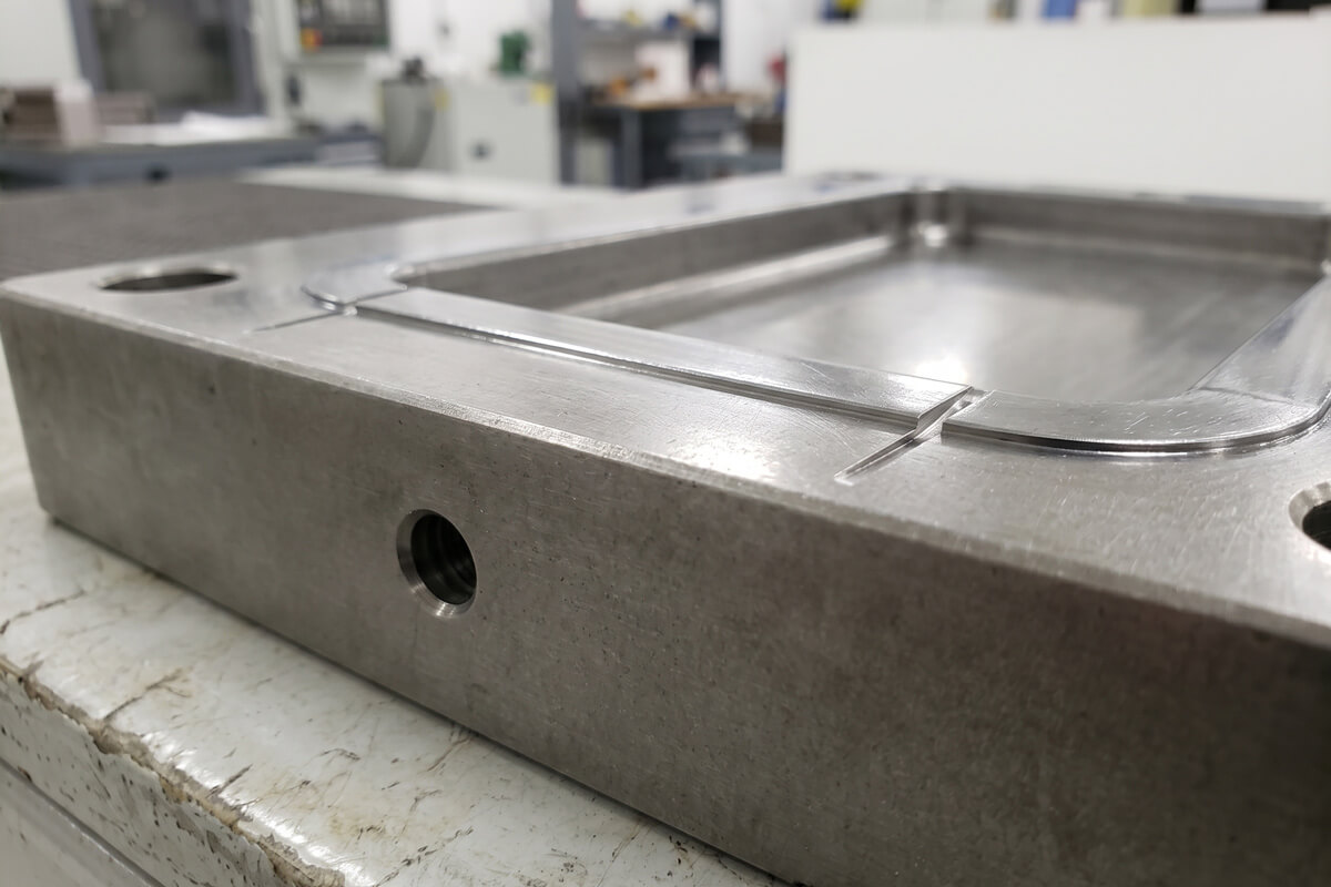
High-speed CNC and mirror EDM improve cavity accuracy and reduce hand polishing, but they rarely remove polishing entirely. In practice:
- High-speed milling cuts complex surfaces with fewer visible tool marks and tighter geometry
- Mirror EDM reaches fine surfaces in corners and ribs that cutters cannot enter
- Optical-grade finishes still need a final polish, and EDM surfaces need their recast layer removed first
- Less manual polishing means less risk of rounding sharp edges and losing tolerance
Our article on precision EDM for complex geometry shows where this applies.
What maintenance practices keep an injection mold in perfect condition over time?
A written preventive-maintenance routine, tied to shot count, keeps a mold in condition. Ask your molder to follow a plan like this:
- After every run: clean the cavity, dry it, apply rust preventive, and store the mold closed in a dry place
- Every 10,000 to 20,000 shots (more often for ABS or POM): clean the vents, lubricate slides and lifters, check ejector pins for sticking
- Every 100,000 shots: strip the mold, inspect wear plates, leader pins and the parting line, and flush the cooling channels
- On the molding machine: check the screw check ring for wear, since a worn ring causes inconsistent packing
Request the shot-count log and maintenance records with each production shipment.
Send your STEP file. We return a mold-spec review covering steel, SPI class, cooling layout and the steel-safe register.
Submit CAD for mold reviewSend the other quotation or mold spec. We flag what is missing, such as steel grade, hardness and class, so you can compare like with like.
See our mold manufacturing