
Ask five buyers what “the injection molding process” means and four of them will describe a six-box diagram they found in a search result. That diagram isn’t wrong, but it skips the part that actually determines whether your parts hit tolerance on shot #1 and shot #100,000 — how consistently the machine repeats each phase, how the cooling stage trades cost against internal stress, and how a factory catches a bad shot before it’s in a shipping box instead of after a customer opens one. This piece walks through the mechanical sequence first, then the three decisions inside that sequence that actually separate a reliable supplier from one running on operator instinct.
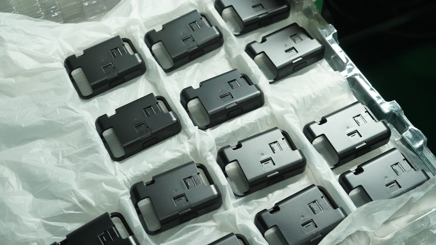
From Clamping to Ejection: What Actually Happens in One Molding Cycle
Before comparing suppliers on process control, it helps to know what’s actually happening inside the machine during those 10 to 60 seconds. If you want the fundamentals of injection molding from a wider angle first, our general process guide covers that; here we’re walking through the cycle itself, stage by stage.
Clamping
Mold halves close, tonnage holds them shut
Injection
Melt fills the cavity at high speed
Packing / Holding
Pressure compensates shrinkage
Cooling
Part solidifies enough to hold shape
Mold Opening
Core and cavity separate
Ejection
Pins or air push the part free
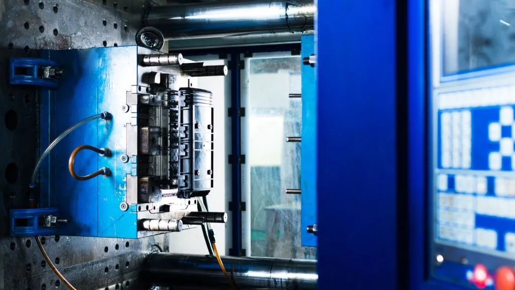
Clamping comes first because the mold has to be held shut hard enough to resist the injection pressure trying to force it open — tonnage is roughly sized to the part’s projected area, which is why a small accessory part might run comfortably on a 50-ton press while a larger structural bracket needs several hundred tons. Injection is the fast part: a screw acting as a ram pushes molten resin into the cavity in one to five seconds, typically filling 95%-98% of the volume before the process deliberately switches from speed control to pressure control. That switch is the boundary between injection and packing — packing/holding then pushes a smaller, carefully controlled amount of additional material into the cavity as the part starts to cool and shrink, which is what actually determines final part weight and density. Cooling takes up the bulk of the remaining time, and once the part is rigid enough to survive ejection forces without deforming, the mold opens along the parting line and the ejector system pushes the finished part free.
One detail that surprises a lot of first-time buyers: plasticizing (also called metering) — where the screw rotates to melt and meter the next shot of resin — usually happens in parallel with the current cycle’s cooling stage, not as a separate block of time tacked onto the cycle. A machine running an efficient process is cooling one part while simultaneously prepping the melt for the next one, which is one of the simplest ways cycle time gets shaved down without touching part quality at all.
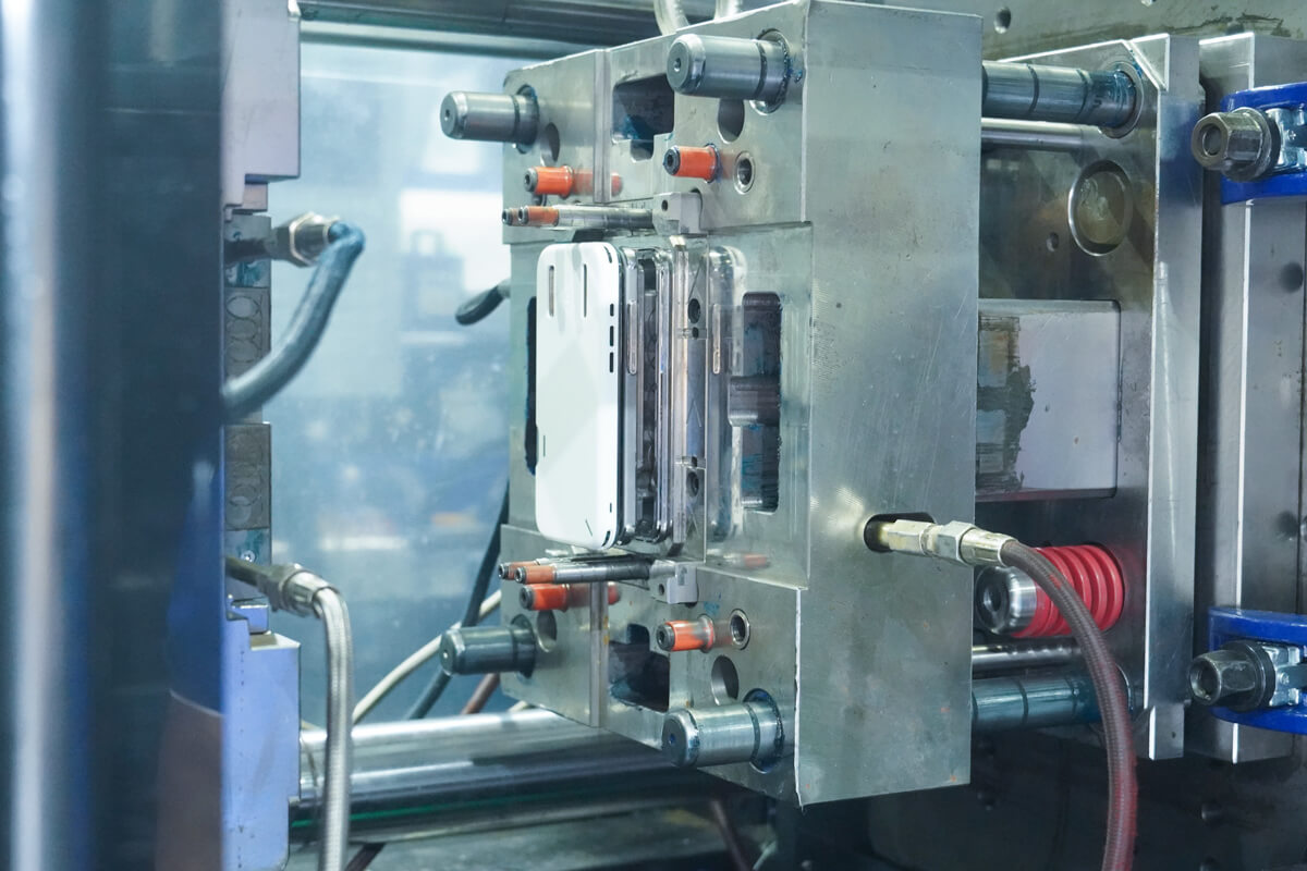
How Scientific (Decoupled) Molding Keeps Shot-to-Shot Consistency Across Long Runs
The sequence above describes the physical stages. What determines whether shot #1 and shot #50,000 come out dimensionally identical is how tightly those stages are controlled — and that’s the real difference between a shop running on an operator’s feel and one running scientific molding.
In conventional setups, fill and pack overlap: the machine transitions from velocity to pressure control based on a fixed timer or position, and any shift in resin viscosity, ambient humidity, or barrel temperature drift changes how much material actually gets packed into the cavity before the gate freezes. Decoupled molding — the methodology developed and popularized by RJG and John Bozzelli — treats filling, packing, and holding as three independently controlled phases instead of one blended step. Filling is controlled by velocity to a defined cavity-pressure threshold, packing is managed separately to hit precise dimensional targets, and holding is timed against a cavity-pressure or gate-seal signal rather than a guess. This separation is what makes cavity pressure control useful for dimensional stability and process capability, particularly when resin viscosity varies between lots (Source: RJG).
The practical upside for a buyer is that the process becomes machine- and operator-independent — it’s defined by data (a cavity pressure curve, a viscosity curve, a validated setup card) rather than a setter’s memory of “what usually works.” That matters most on long runs and multi-shift operations, where the person babysitting the machine at 2 a.m. isn’t the same one who set it up.
What to actually ask a supplier to confirm this:
- Do they run a viscosity curve study during tooling validation, and can they share it?
- Is cavity pressure logged per shot, or only checked occasionally with a handheld gauge?
- Can they produce a process capability (Cpk) report on your critical dimensions from the initial production run, not just the first-article sample?
A factory that can answer all three without hesitation is running the process by data. One that can only describe “our experienced setter” is still running it by feel — which is fine for a low-stakes commodity part, and a real risk for anything with tight fits or a long production run. This is the kind of documentation that should also show up in your quality assurance package alongside dimensional inspection reports.
Cooling Time: The 60%–80% of Your Cycle That Decides Both Cost and Warpage
Cooling is the slow part of the cycle for a simple physical reason: plastic is a poor conductor of heat, and the mold has to pull heat out through the full wall thickness — not just the surface — before the part is rigid enough to survive ejection without distorting. As a rough rule of thumb, cooling time increases with roughly the square of wall thickness, so a wall that’s twice as thick can need close to four times as long to cool safely. That relationship is why wall thickness decisions made early in design quietly set your per-part cost months later at the machine.
Why this can’t just be rushed:
Pulling a part before the core has solidified doesn’t save real time — it traps residual stress that surfaces later as warpage, sink, or cracking under load.
The legitimate way to shorten cooling isn’t ejecting earlier, it’s designing the mold to remove heat faster and more evenly — through mold temperature control, coolant flow rate, and channel layout. Conventional straight-drilled cooling channels can leave hot spots in deep ribs or cored features, forcing the whole cycle to run longer just to bring those thick sections down to temperature. Conformal cooling channels, machined or additively manufactured to follow the part’s actual geometry, keep the coolant closer and more evenly distributed. In one documented tooling case, switching a mold’s cooling insert to a conformal, additively manufactured design cut cooling time from 20 seconds to 6 seconds, reducing total injection cycle time by 20% with no measurable impact on part quality (Source: voestalpine).
For most accessory-class parts, that level of tooling investment only pays back at real volume — but the underlying principle holds at any scale: a proper mold cooling layout, balanced through flow simulation before steel is cut, is a legitimate cost lever. Skipping the analysis and just cutting the cooling timer on the machine is not.
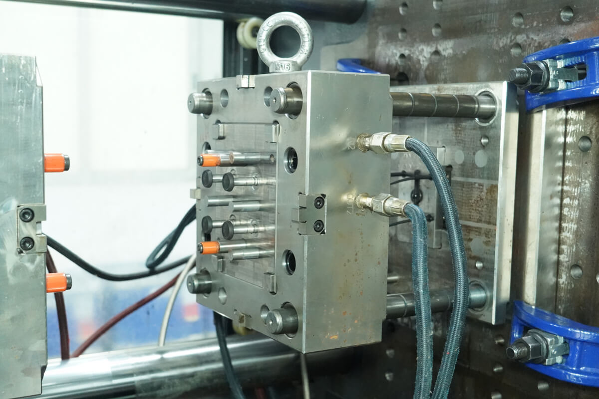
Catching Defects Before They Reach the Shipping Box: In-Process Quality Controls
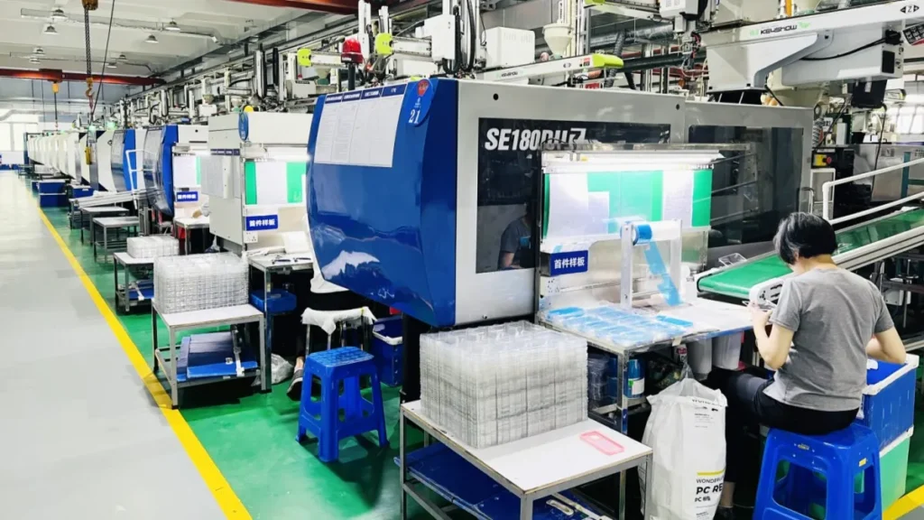
At a cycle time of 15-30 seconds, a single machine can produce a part every half minute around the clock. Human visual inspection simply can’t keep pace with that rate without sampling — which means a pure eyes-on-parts QC plan has a structural blind spot, not just a risk of tired inspectors. The parts that get missed are usually the ones that matter most: a short shot or a hairline flash that doesn’t show up until it jams an automated assembly line on your end.
Two technologies close that gap directly at the point of production:
- Cavity pressure transducers — every shot’s pressure curve is compared against a validated reference (“golden”) curve in real time. A curve that falls outside set thresholds flags that specific shot as suspect the instant it happens, not after it’s counted and boxed.
- Machine vision (CCD) systems — cameras mounted at the mold or on the takeout robot check dimensions, gate condition, and surface defects on every part, automatically diverting anything out of spec before it reaches the conveyor.
The part that matters for a buyer evaluating a supplier isn’t whether these exist somewhere in the plant — it’s whether they’re tied to an automatic containment action. A pressure sensor that only logs data for someone to review the next morning doesn’t stop a bad part from shipping. One connected to a robot, reversing conveyor, or flipper chute that physically removes the suspect part the moment the deviation is detected does. That distinction is worth asking about directly, and it’s the same category of defect risk covered in more depth in our piece on common molding defects and remedies.
Cycle Time and Cavitation: What It Actually Means for Your Lead Time
Once you understand where the time in a cycle actually goes, estimating real output becomes a straightforward calculation — and a useful way to sanity-check a supplier’s capacity claims against reality.
Rough daily output formula
Daily Output = (Running Hours × 3600 ÷ Cycle Time) × Cavities × Uptime%
Worked example: a 4-cavity mold running a 12-second cycle, operating 20 hours a day at 90% realistic uptime, produces roughly (20 × 3600 ÷ 12) × 4 × 0.9 ≈ 21,600 parts per day. Change any one variable — a supplier quoting a 2-cavity tool instead of 4, or assuming 24-hour uptime with no allowance for changeovers and maintenance — and that number moves by a lot. This is worth running yourself rather than accepting a single “parts per hour” figure at face value, since two suppliers quoting the same cycle time can still differ enormously in real throughput depending on cavitation and actual uptime.
Cavitation itself is a tradeoff, not a free upgrade: more cavities multiply output per cycle, but they also raise tooling cost and make it harder to hold cavity-to-cavity balance — exactly the consistency problem that scientific molding and cavity pressure monitoring exist to manage. A higher cavity count only pays off if the process controls to maintain it are actually in place. For a deeper look at how these variables roll into total program cost, our mold cost breakdown goes further into tooling and per-part pricing specifically.
Frequently Asked Questions
What are the 6 major steps in the plastic injection molding process?
The six core steps are clamping, injection, packing/holding, cooling, mold opening, and ejection.
- Clamping — the mold halves close and clamp tonnage holds them shut
- Injection — molten plastic is pushed into the cavity at high speed
- Packing/holding — additional controlled pressure compensates for shrinkage as the part begins to cool
- Cooling — the part solidifies enough to hold its shape
- Mold opening — the mold halves separate along the parting line
- Ejection — the finished part is pushed free by the ejector system
Plasticizing (melting the next shot of resin) technically happens in parallel with cooling, which is why some sources count it as a seventh step and others fold it into the cycle description.
What is the difference between injection pressure and holding/packing pressure?
Injection pressure drives the first, high-speed fill stage, controlling how fast and how far the melt travels into the cavity. Holding/packing pressure is the lower, second-stage pressure applied afterward, which pushes a small amount of additional material into the cavity as the part cools and shrinks. Injection pressure is mostly responsible for flow-related defects like short shots or flow lines; holding pressure primarily determines final part weight, density, and shrink-related defects like sink marks. A sink mark is almost always a packing pressure or timing issue — not an injection pressure one — which is a common troubleshooting mix-up.
Why is the cooling phase the longest step in the injection molding process?
Because plastic conducts heat poorly, and the mold has to pull heat out through the entire wall thickness before the part is rigid enough to eject safely. Cooling time increases roughly with the square of wall thickness, so a section twice as thick can need close to four times as long to cool. That’s why cooling typically eats up 60%-80% of a full cycle even though injection itself takes only a few seconds, and why wall thickness choices made during design directly set your unit cost later.
What happens during the plasticizing or metering stage in an injection molding machine?
The screw rotates, conveying resin pellets forward while barrel heater bands and the screw’s own mechanical shear melt them into a homogeneous melt. As it rotates, the screw retracts, accumulating a precisely metered shot volume in front of its tip for the next injection. Barrel temperature and screw speed both matter here — too much heat or shear can degrade the polymer, while too little leaves unmelted material that shows up as streaks or weak spots in the finished part. On a well-run process, this stage overlaps with the previous shot’s cooling time, so it doesn’t add extra time to the overall cycle.
How long does a single injection molding cycle take on average?
Most production cycles run somewhere between 10 and 60 seconds, depending largely on part wall thickness and size. A small, thin-walled accessory part might cycle in 10-15 seconds, while a larger or thicker structural part can take 45-60 seconds or more. To estimate real daily output, multiply (3600 seconds ÷ cycle time) by the number of cavities and by a realistic uptime percentage — not the machine’s rated cycle time alone, which assumes zero downtime.
How does the ejection phase work, and how do ejector pins avoid leaving marks on cosmetic surfaces?
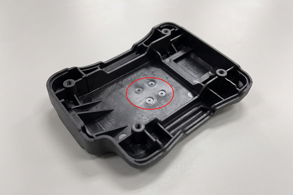
After the mold opens, an ejector plate drives a set of pins, blades, or air poppets forward to push the finished part off the core side of the mold. Each pin leaves a small witness mark where it contacts the part, so toolmakers deliberately place ejector pins on the non-cosmetic B-side, spread across ribs, bosses, and structural features rather than visible flat surfaces. For parts where every visible face matters, options like ejector sleeves around bosses, stripper plates, or air-assisted ejection spread the force more evenly and avoid the sharp point-contact a standard pin leaves behind.
Not sure your part’s cycle time and cavity count add up?
Send us your CAD and target volume — we’ll walk through cavitation, cooling layout, and a realistic cycle time estimate with your project engineer.