
A sink mark is a shallow dent on the surface of a molded part, usually over a rib, boss or thick section. It forms when that thick spot keeps shrinking after the surface has frozen and nothing is left to feed it. The geometry rules that prevent it are in our guide on how to design for injection molding. This article is for the sample already on your desk: how to confirm what you have, which fix to try first, and when the steel has to change.
As a plastic injection molding manufacturer, we see the same pattern at many T1 reviews: a small dimple, an argument about whose fault it is, and three settings changed at once. The order below avoids that.
Sink Mark or Void? Confirm What You Have First
Both come from the same shrinkage. The skin freezes first and the core keeps shrinking. If the skin is soft it is pulled inward, which gives a sink. If it is stiff enough to hold, the core pulls apart and leaves an internal void instead (Source: RapidDirect, 2025). A void never shows on the surface, but it weakens the part. Before changing anything, check three things:
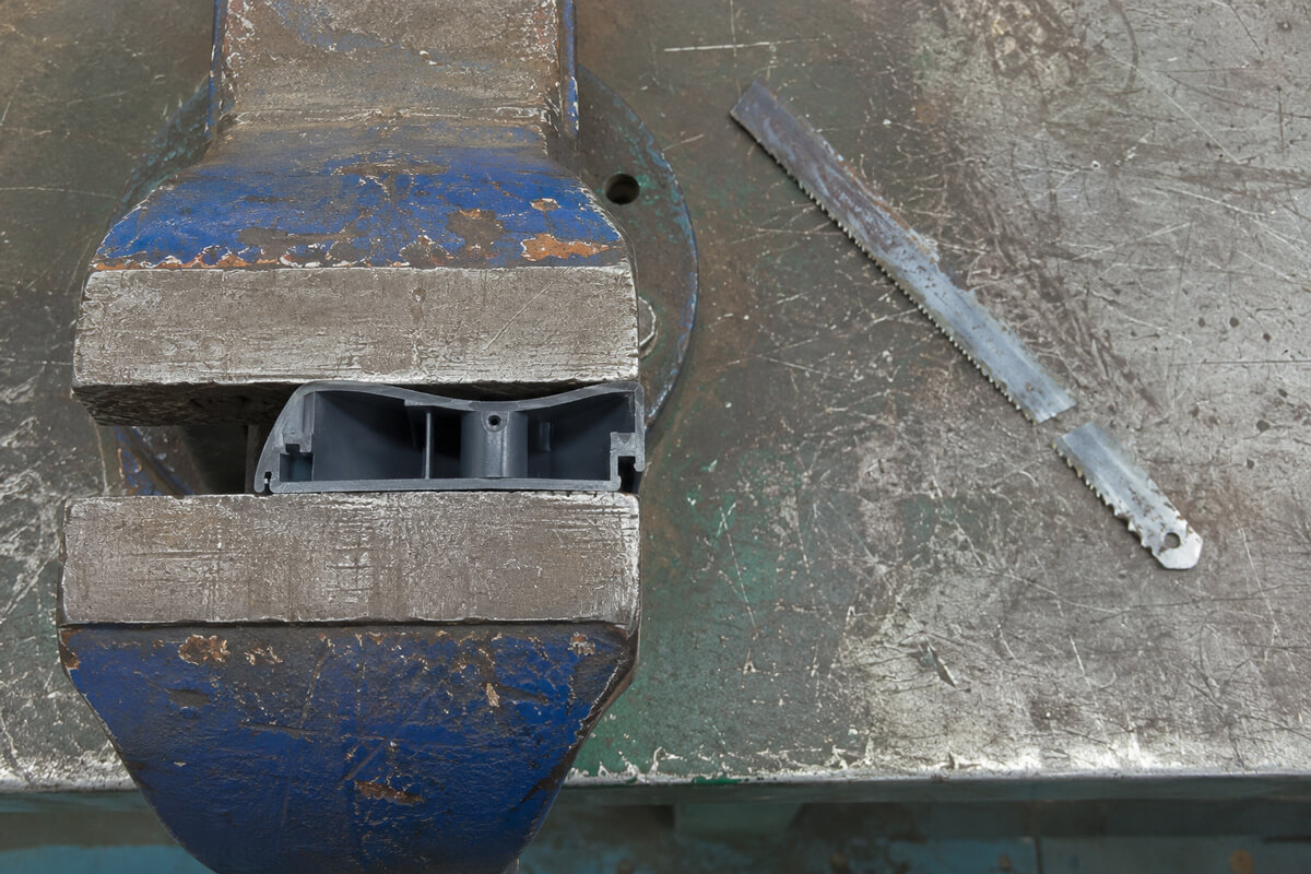
- Section the part through the thick area. A hollow in the core means a void, not just a surface problem.
- Weigh it against a good part from the same cavity. A part that was not packed out is often lighter.
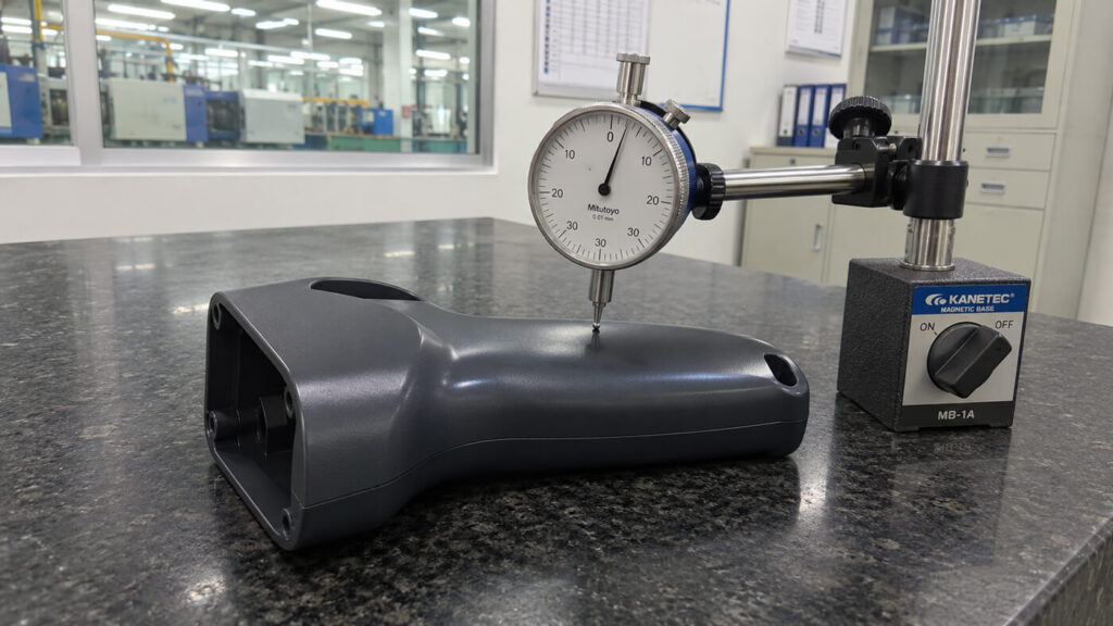
- Measure the depth with a CMM or dial indicator, so you have a number to track from one trial to the next.
Moisture bubbles are a different defect; see what causes bubbles in plastic injection molding. Other look-alikes are covered in our overview of plastic molding defects and remedies.
Why Sink Marks Form: Shrinkage That Packing Did Not Cover
Packing is the phase after fill when extra melt is pushed in to replace shrinkage. It only works while the gate is open and the path to the thick section is still molten. Sink marks appear when that window closes too early or the demand is too large. Four causes account for most cases:
- Geometry: ribs and bosses thicker than about 40–60% of the adjoining wall, or an isolated thick block
- Packing: hold pressure too low, or hold time shorter than the gate seal time
- Gate and runner: a small or distant gate that freezes before the thick section is packed
- Temperature and material: semi-crystalline resins such as PP, PE, PA and POM shrink more than amorphous ABS or PC, and a hot core takes longer to solidify
Fix Order at T1: Packing, Then Temperature, Then Steel
Fixes get costlier as you go down this list, so work in order and change one variable at a time.
Step 1: Run a gate seal study
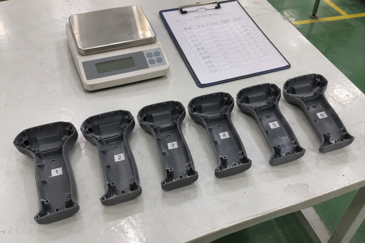
Hold time should last until the gate freezes, and no longer. Mold several shots at increasing hold times, weigh them, and plot weight against time. Weight climbs while the gate is open, then plateaus; the time just before the plateau is the gate seal time. FirstMold’s guide suggests setting hold 0.5–2 seconds beyond it . Too short leaves dents near the gate. Too long adds internal stress and gate protrusion.
Step 2: Raise hold pressure in small steps
Too little pressure leaves the core under-compressed, so it shrinks freely and sinks. Too much brings flash, warpage and residual stress, which hurts precision parts and parts that will be plated. Raise it until the sink disappears, then stop. Typical starting points, as a share of injection pressure:
Rule-of-thumb starting points, not limits; bars show the upper end on a 0–100% scale. Source: FirstMold’s 2026 update.
Check the switchover point as well. The same guide puts it at about 95% full as a starting point, and about 98% for thin-wall parts.
Step 3: Balance temperature, one setting at a time
Melt and mold temperature pull in opposite directions. A hotter melt flows further but shrinks more. A cold mold freezes the gate early, while a hot one leaves the core molten longer. Stay inside the resin datasheet window and move in small steps. If a change only trades one defect for another, go to the tool.
| Lever | Why it helps | What it costs |
|---|---|---|
| Hold time to gate seal | Keeps feeding the part until the gate freezes | Longer cycle, stress and gate protrusion if overdone |
| Hold pressure | Compresses the melt to offset shrinkage | Flash, warpage, residual stress |
| Cooling time | Lets thick sections solidify before ejection | Cycle time |
| Lower melt temperature | Less total shrinkage | Harder fill, earlier gate freeze |
| Mold temperature | Sets how long the gate and core stay hot | Gloss and cycle time shift |
When Process Hits Its Limit: Tooling Changes That Work
Process changes can reduce a design-caused sink but rarely remove it. If pressure is already at the flash limit and the dent remains, the answer is in the tool:
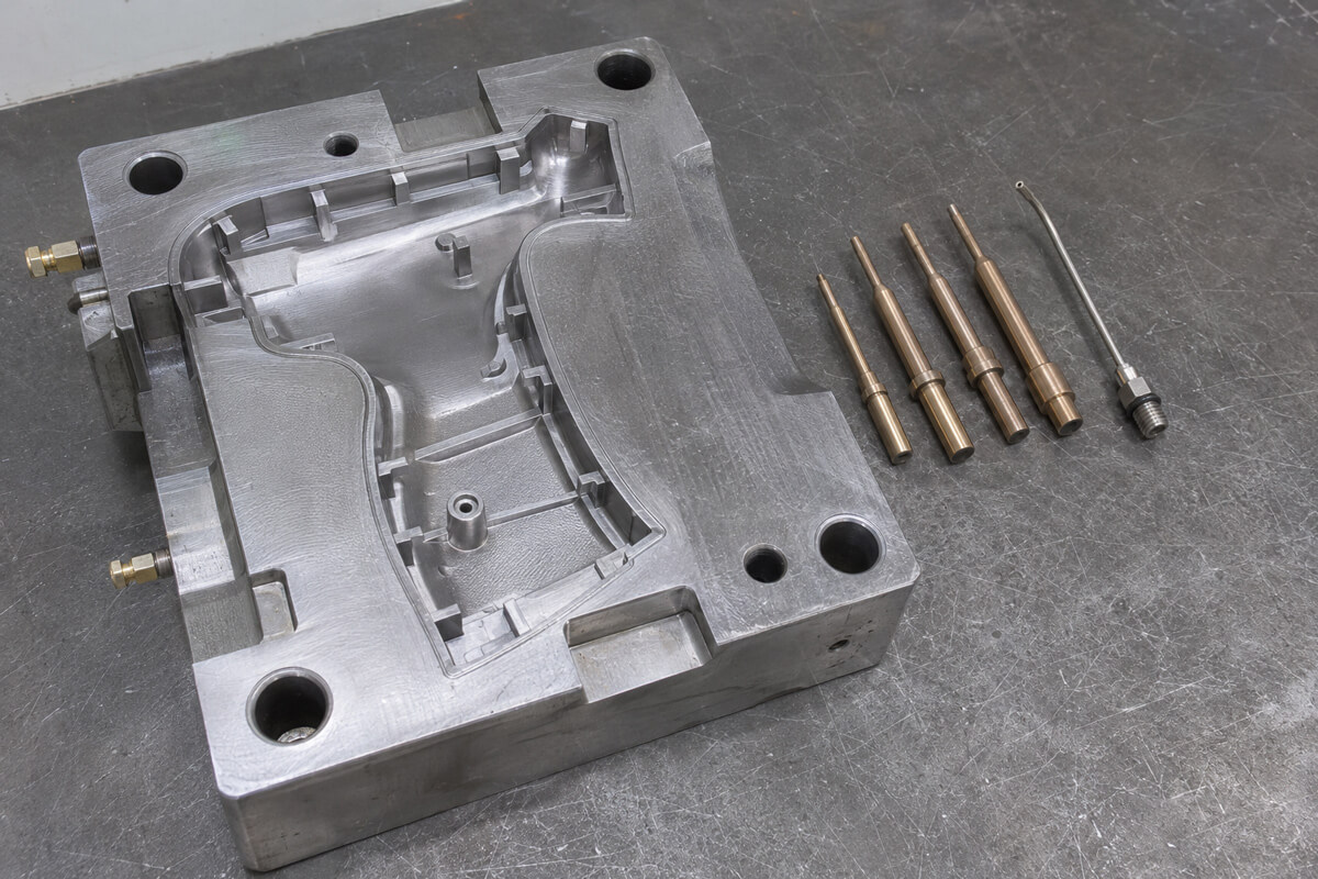
- Gate: move it to the thick section or enlarge it, so the thick spot is packed before the gate freezes. Avoid a path that forces melt through a thin wall to reach a thick one. A pinpoint or tunnel gate freezes earlier than an edge gate.
- Cooling: pull heat out of the boss with a beryllium-copper pin or insert, a bubbler or a baffle, so core and skin solidify closer together.
- Core pins: a protruding pin can thin the wall opposite a boss, but results vary by resin, so trial it before committing.
- Wall: core out the thick section. This is a design change and needs steel or an insert.
Most of these are small jobs when caught at T1. Enlarging a gate removes steel, and a cooling insert needs a modest pocket. On a rapid tooling program, our MUD route gets T1 samples out in as little as 10 days, so a second iteration costs days, not weeks. Larger revisions follow our injection mold manufacturing workflow.
Hiding What You Cannot Remove: Texture, Color and Acceptance
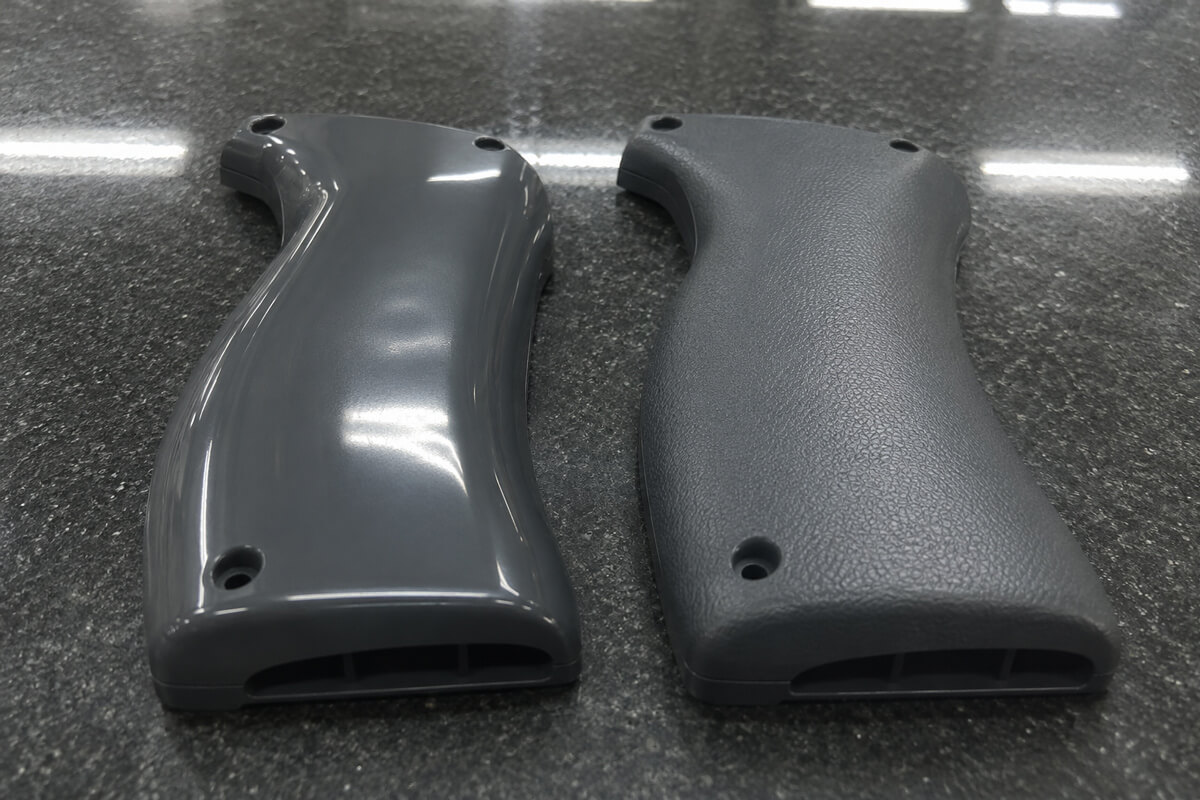
Visibility depends on depth, color and surface, and even small sinks catch light on a glossy or dark part (Source: RapidDirect, 2025). A textured surface scatters that light, which is why leather-grain or VDI 3400 etching is a practical tool and not just decoration. In our MagSafe camera grip teardown, a contoured PC+ABS handle was cored to a uniform 2.0–2.2 mm wall with a grid of internal ribs, and leather-grain texture hid the parting line. The same texture also masks shallow sinks.
Texture never fixes a void, or a sink on a flat polished face. Write acceptance into the spec instead: mark show surfaces on the drawing, set a maximum measured depth for each zone, and keep a signed limit sample with the tool.
Frequently Asked Questions
What causes sink marks in injection molding?
Sink marks are caused by a thick section shrinking after the surface has frozen, without enough packing to replace the lost volume. The usual triggers are:
- Ribs, bosses or thick blocks
- Hold pressure too low, or hold time shorter than gate seal
- A gate that is too small or too far from the thick area
- A high-shrink resin
How do you fix sink marks in injection molding?
Fix them in this order, changing one variable at a time:
- Run a gate seal study and set hold time just beyond gate seal
- Raise hold pressure in small steps until the dent goes
- Adjust melt and mold temperature within the datasheet range
- Enlarge or move the gate, or improve cooling at the thick area
- Core out the thick section, or mask what remains with texture
What is the difference between a sink mark and a void?
A sink mark is a dent on the surface, while a void is a hollow inside the part. Both come from the core shrinking after the skin freezes. A soft skin collapses inward and makes a sink; a stiff skin holds and the core pulls apart. Cut a section through the thick area to tell them apart.
Do sink marks affect part strength?
Usually they are cosmetic, but they signal a thick, under-packed section that may hide a void, and voids reduce strength and stiffness. Section a sample through the thick area before accepting a sink as cosmetic only.
Which materials are most prone to sink marks?
Unfilled semi-crystalline resins such as PP, PE, PA and POM are most prone, because they shrink more than amorphous ABS or PC. Glass-filled grades shrink far less. Check datasheet shrinkage early; our material selection guide compares the common options.
How do you avoid sink marks through design?
Keep ribs and bosses at 40–60% of the adjoining wall, core out thick solid sections, round inside corners to at least 25% of wall thickness, and change thickness gradually at about 3:1. The full rules are in our guide on how to design for injection molding.
Got a T1 sample with sink marks?
Send photos of the dent, the part drawing and your resin grade, or your STEP file if the tool is not cut yet. We will tell you whether it is a packing, gate, cooling or design problem, and what a fix would take. We sign an NDA before you share files. Our custom injection molding services team handles the review.
Send us your sample photos