
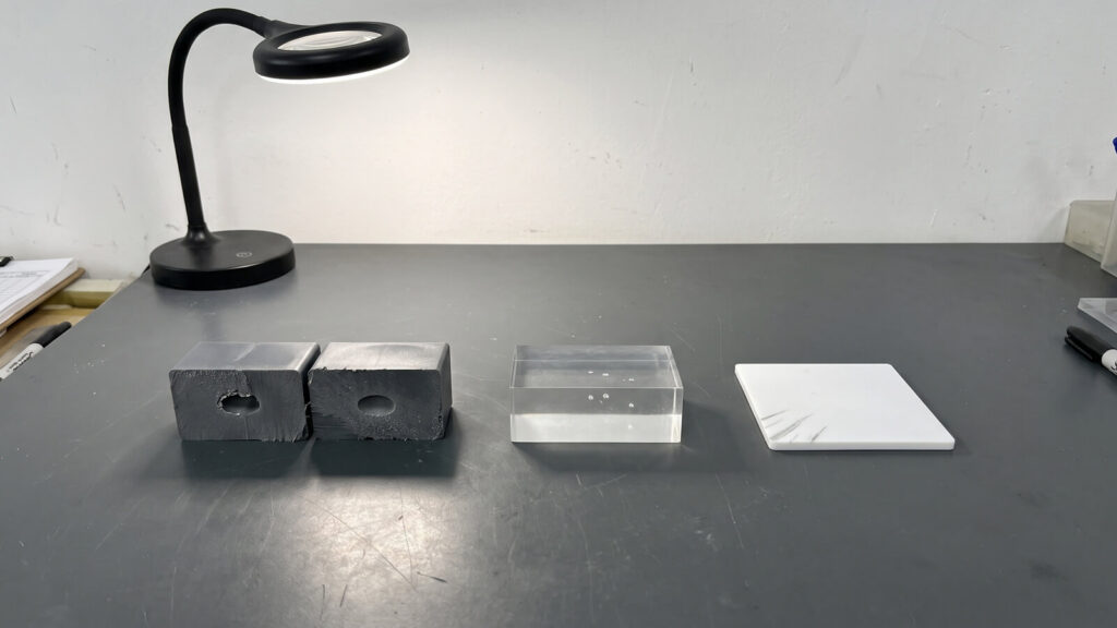
“Bubbles” in an injection molded part can mean two defects with opposite fixes. One is a vacuum void, a hollow pulled open by shrinkage in a thick section. The other is trapped gas: air, moisture vapor or decomposition gas caught in the melt. If you treat a void as a drying problem, you can dry resin for days with no result. This guide shows how to tell them apart, why thick walls void, and what to do when machine settings alone cannot clear gas, including who normally owns the fix. For the wider defect list, see our molding defects and remedies page.
Step 1. Is It a Vacuum Void or a Gas Bubble?
A vacuum void forms when the core of a thick section keeps shrinking after the surface has frozen, so the material pulls away from itself. Gas bubbles are different: the cavity contains air or vapor, often at high pressure. The test most molders trust is gentle heating. Warm the area on a scrap part until the surface softens. A gas bubble swells and may pop; a vacuum void collapses or dimples, as atmospheric pressure presses on the softened wall. Do this near an extraction point and on a fresh part, because Plastics Technology reports that air can migrate into a void over hours, and an aged part can give the wrong answer.
Shape and position are hints, not proof, and the same article warns that they can mislead. In opaque parts, saw the part through and sand the cut face, or send it for CT scanning. Then compare the clues:
| Clue | Vacuum void | Trapped air | Moisture or degraded resin |
|---|---|---|---|
| Usual location | Thickest section, boss, rib root | Last area to fill, weld lines | Along the flow path, often near the gate |
| Companion sign | Sink mark on the surface | Burn marks at the vent | Silver streaks (splay) |
| Warm test (fresh part) | Collapses | Expands | Expands |
| More packing | Shrinks or clears | May shrink, rarely clears | No change |
| What helps instead | Gate, packing, wall design | Venting, slower fill, gate position | Drying, lower melt temperature |
Section three consecutive parts from a stable run, not one, because a single void can be random. Record where each bubble sits relative to the gate, measure its size, and photograph it beside a ruler. With that evidence, buyer and supplier argue about the same facts instead of opinions.
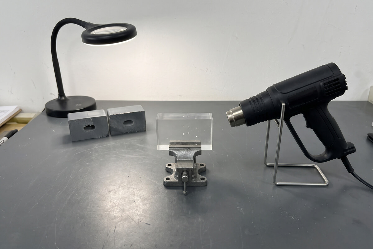
Step 2. Thick Walls: Why Voids Form and What Packing Can Do
In a thick section the skin freezes first while the core is still hot and still shrinking. With no new melt coming in, the core pulls inward and a void opens. Walls around 6 mm (0.25 in) and thicker, boss bases and rib roots are the usual sites. A void inside a load-bearing part is not cosmetic: it reduces the effective cross-section and can concentrate stress, with impact and fatigue loading the most sensitive. How much strength is lost depends on void size, position and load path, so there is no universal number. For structural parts, section or CT-scan first articles and agree an acceptance rule, such as no voids above a set diameter in defined high-stress zones.
Packing can fix voids, but only while the gate is still open. A practical order of work:
2. Raise hold pressure within that window, watching for flash.
3. Adjust temperature. A warmer mold keeps the skin soft longer; excess melt temperature adds shrinkage.
4. Open the gate or move it to the thick section so pressure can reach the core.
5. Stop when flash appears and the void remains. That is a design problem, not a setting.
Material plays a part too. Hard, tough amorphous resins such as PC, acrylic and PS are the classic void makers, because a stiff skin forms early and resists collapsing into the shrinking core. Higher-shrink semi-crystalline resins often show the same shrinkage as a surface sink instead. Either way, the thick section is the cause, not the plastic.
The permanent fix is geometry: core out heavy sections, keep walls uniform, and hold ribs and bosses to roughly half to 60% of the adjacent wall, with smooth transitions. Fill from thick to thin, so the heavy section is not starved. Our design for injection molding guide covers wall rules. Mold-flow simulation can flag thick spots and gate freeze time before steel is cut, which reduces risk, though first samples still confirm it, as we explain in our perfect tooling article.
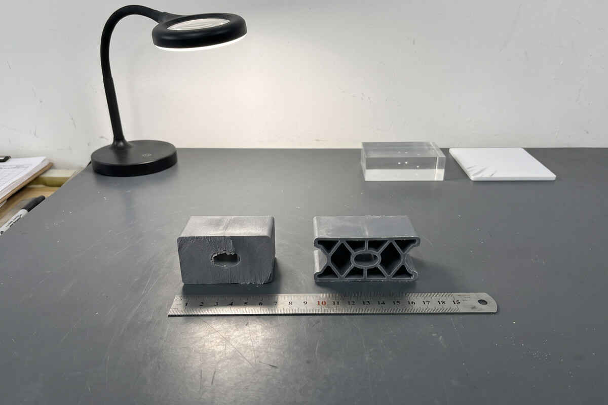
Step 3. Trapped Gas: When Machine Settings Run Out
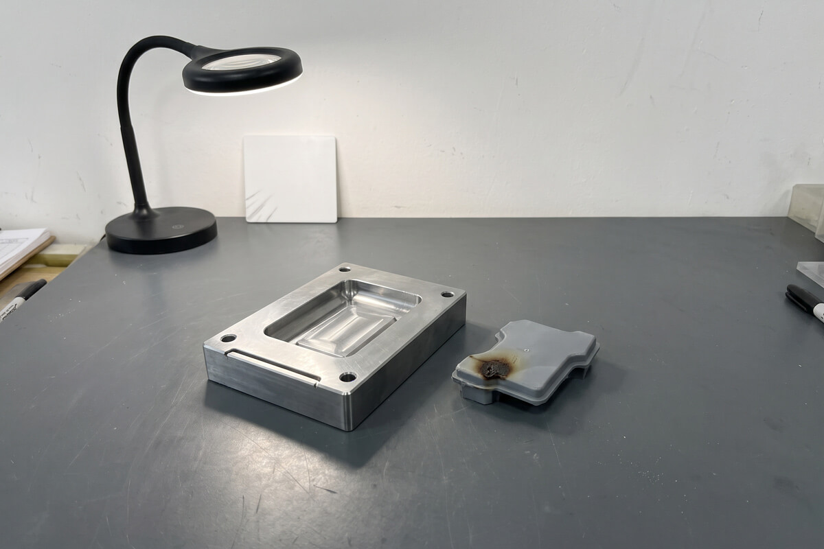
Once the fill speed, back pressure, temperature and drying have been checked (see the FAQ below), persistent gas points to the tool. Trapped air collects in the last area to fill, at weld lines, at rib ends and in deep bosses. Packing pressure may shrink such a bubble but will not remove it, because pressure does not vent gas.
Rule out the machine side first, and record the result: drying log and dew point, melt temperature inside the datasheet range, back pressure and decompression, the injection speed profile near the gate and at the end of fill, and the switchover position. If each has been tried and the bubble stays in the same place, the tool is the next suspect.
What the toolmaker should change
Venting. Add or deepen vents at the last-to-fill points, then check the depth against the resin. Thin-flowing materials such as nylon flash through a deep vent, so they need very shallow ones; the range cited in our tooling article runs from about 0.013 to 0.076 mm depending on resin. A short vent land followed by a deeper relief channel carries the gas out. Where a groove will not fit, use vent pins, venting ejector pins or porous inserts. Vents also clog with residue, so cleaning belongs in the maintenance plan.
Gate and flow. Move the gate so the melt does not fold back on itself and trap air. A tiny gate that jets melt into the open cavity creates folds; a fan or larger gate calms the front. An overflow well at the end of fill can carry the last air and cold material out of the part.
Who usually owns the fix
Disputes start when a supplier blames “the plastic”. Ask for the experiments behind the diagnosis, then use this as a guide:
| Evidence | Likely root cause | Who normally acts |
|---|---|---|
| Bubbles at last-to-fill, burn marks, slower speed helps only partly | Poor venting | Toolmaker: vents, vent pins |
| Void in the thick section, still there when packing reaches flash | Wall thickness and gate | Design owner and toolmaker together |
| Scattered bubbles and splay that clear after drying | Moisture or material handling | Molder |
| Snake-like folds or discoloration at the gate | Jetting or shear at the gate | Molder first, then toolmaker |
Agree in the contract how many trial rounds and tool modifications are included, so a vent change is not a negotiation; our guide to reading molding quotes explains how. And because voids hide inside opaque parts, ask about sectioning or CT on first articles in our quality assurance process.
Quick Answers on Bubbles in Injection Molding
What is the difference between a vacuum void and a gas bubble in injection molding?
A vacuum void is an internal hollow created by shrinkage in a thick section, and it holds almost no gas. A gas bubble contains air, moisture vapor or decomposition gas. They respond to opposite fixes, so confirm the type with the warming test above before changing settings.
How do you stop bubbles in thick plastic injection molded parts?
Treat them as shrinkage first: study gate seal time, extend hold within it, keep the mold warm enough for the skin to stay soft, and enlarge or relocate the gate. If a void remains at flash-level packing, core out the section or thin the wall.
Does trapped moisture in resin cause bubbles in finished plastic parts?
Yes, with hygroscopic resins such as PA, PC, PET, PBT and PMMA. Absorbed water turns to steam in the barrel and leaves bubbles and splay. Follow the grade datasheet for temperature and time (PC, for example, is typically dried to about 0.02% moisture), use a desiccant dryer with a dew point near -40 °C, and check dryer logs. Regrind needs the same drying. Our silver streak and plastic type guides cover this further.
How does injection speed and back pressure affect bubble formation?
Too fast, and the melt can jet through the gate and fold air in, or compress air at the end of fill until it burns. A profile that fills slowly near the gate and at the last 10 to 20% of the cavity often helps. Too little back pressure leaves air in the melt; too much adds shear heat and degradation gas. Excessive suck-back can also pull air in at the nozzle. Change one parameter at a time and watch the screw cushion.
Why do bubbles appear near the gate of an injection molded part?
Typical causes are jetting, shear heating in a gate that is too small, and moisture streaks that radiate from the gate. Look at the pattern: a snake-like fold points to jetting, brown discoloration to shear, and silver radial streaks to moisture. A hot runner valve gate that leaks air is another possibility; see our hot runner page.
Can poor mold design cause trapped air bubbles in plastic molding?
Yes. Missing or shallow vents, a gate that traps air behind the flow front, and sudden wall changes all trap air no matter how the machine is set. The ownership table above shows how to separate a tool issue from a design or material issue.
Send us three things and we will tell you whether it looks like a void or gas, and what to change first:
2. Resin grade and drying record
3. Your STEP file and wall-thickness callouts