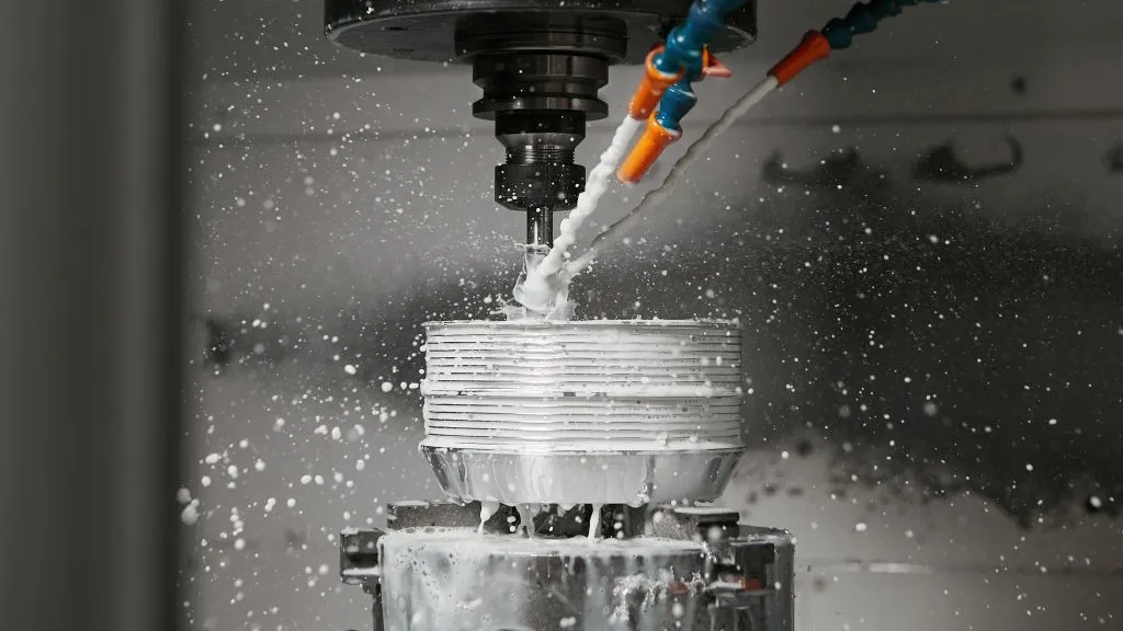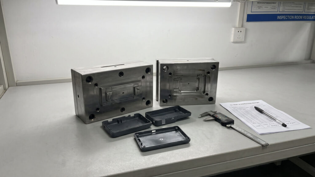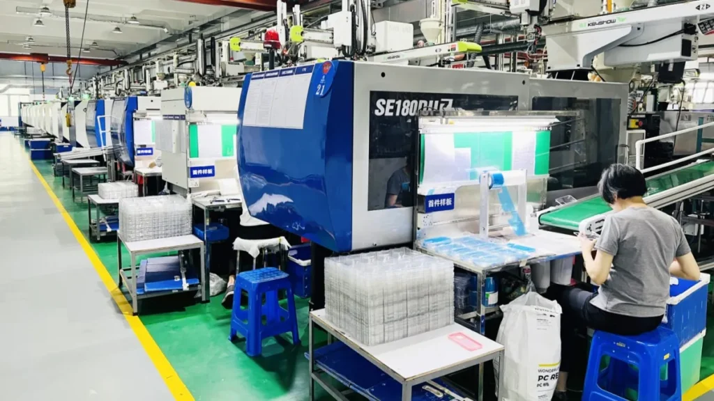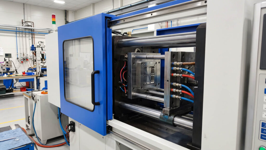

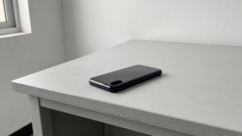
A weld line is the seam left where two streams of molten plastic meet inside the cavity and fail to fuse completely. Some people call it a knit line. Any part with a hole, an insert or more than one gate will have at least one. On a glossy black phone case it shows up as a pale scar beside the camera cutout. On a snap-fit clip it is where the part cracks first.
Buyers often ask us how to “get rid of” weld lines. That is usually the wrong target. The better questions are where the line will sit, how visible it will be, and whether it crosses a load path. As a plastic injection molding manufacturer focused on cosmetic accessory parts, we work through them in a fixed order: understand it, move it, heat it, vent it, and only then hide it.
- A visible line, dark streak or color shift on a show surface
- Usually solved by gate position, hotter fronts, or a finish that masks it
- Cracks at holes, bosses or snap-fits under load or in assembly
- Needs gate, venting and packing fixes, and sometimes a different resin
How a Weld Line Forms, and How It Differs from a Meld Line
Melt advances in a fountain pattern: the core of the flow runs faster while the skin touching cold steel freezes. When two fronts meet, they touch at mid-wall first, then fill outward and leave a V-shaped groove on the surface. If that groove holds trapped air, or the fronts arrive too cold, the surface shows a line and the bond underneath is weak (Source: FirstMold).
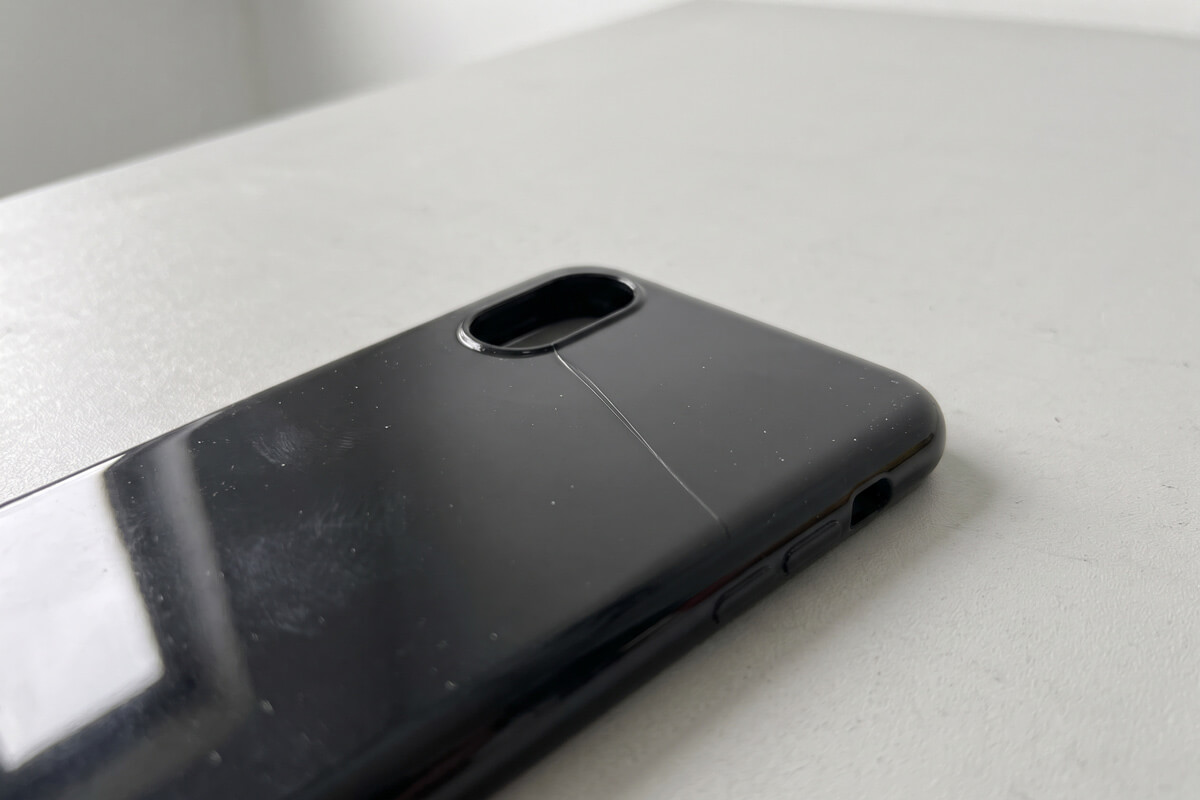
Not every seam is a true weld line. When two fronts collide head-on at a sharp angle, below roughly 135 degrees, the interface is a weld line. When they merge at a shallow angle and flow together, it is a meld line, which is normally stronger and far less visible (Source: Prolean, 2026). Most people use “weld line” for both, and so will we.
The usual hiding places are easy to predict:
- Behind core pins that form holes, such as camera, button and speaker cutouts
- Behind bosses and inserts
- Where two gates feed the same cavity and their fronts meet
- At wall-thickness transitions
- At the last point to fill, far from the gate
Causes of Weld Lines: Four Things to Check Before Touching the Machine
Which resins show weld lines most
Resin choice changes both how visible the line is and how much strength you lose. Prolean’s 2026 comparison rates amorphous and glass-filled grades as the most sensitive. The bars follow that qualitative ranking and are not measured values.
A dark, glossy ABS or PC part with a hole pattern is the hardest combination we see on accessory projects. PP forgives weld lines but rarely matches that gloss or paintability.
The Fix Order: Move the Line, Heat the Fronts, Vent the Cavity, Then Mask It
Fixes get more expensive to live with as you go down this list. A well-placed gate costs nothing per part, a hotter mold costs cycle time on every shot, and paint costs money on every piece.
Step 1: Relocate the line with gate position and part layout
Gate location decides where the fronts meet. On a phone case, the melt splits around the pin that forms the camera hole and rejoins right behind it, so many first samples show the seam exactly where customers look first. Shifting the gate so the front finishes toward a lower edge or inner lip moves the line out of sight without touching the process.
FirstMold’s guide lists useful mold-side rules. Pinpoint and sub-gates lose a lot of pressure, while side and fan gates lose less. On large parts, extra gates shorten the flow path so fronts meet hotter; on small parts, fewer gates means fewer fronts. In a hot runner mold, sequential valve gates open one after another, so no weld forms between them. See hot runner injection molding for when that tooling cost pays off.
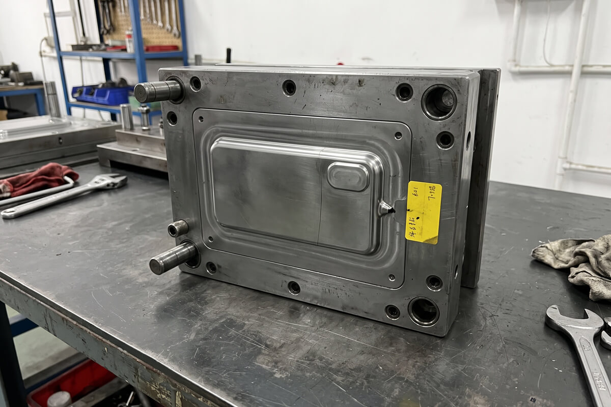
Part layout helps too: fewer holes, round holes aligned with the flow, even wall thickness. Moving a gate after the steel is cut usually means welding and re-machining an insert, so settle it in DFM. While a design is still being validated, our rapid tooling route (MUD) can deliver samples in as little as 10 days, so testing a second gate position stays cheap. For production steel, the same decisions carry into our injection mold manufacturing workflow.
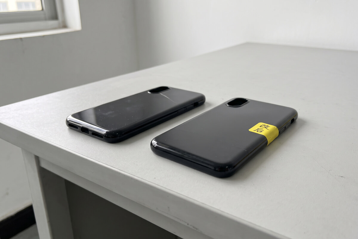
Step 2: Heat the fronts with process settings, and know what each costs
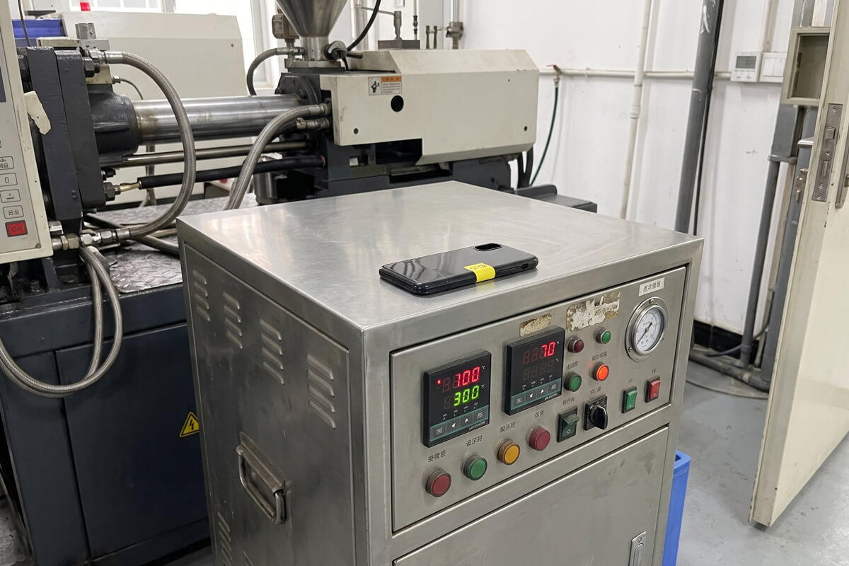
Process changes need no tooling work, but each has a price. Stay inside the resin datasheet window; going beyond it trades a weld line for degradation. We change one variable at a time and log it, because three tweaks at once teach you nothing.
| Lever | What it does | What it costs you |
|---|---|---|
| Raise melt temperature | Thins the melt so fronts arrive hotter | Degradation, color shift, longer cooling |
| Raise mold temperature | Delays skin freeze so fronts can fuse | Longer cycle; can shift gloss and shrinkage |
| Increase injection speed | Fills faster so fronts stay hot | Burn marks at vents, jetting, flash |
| Increase packing pressure | Compresses and strengthens the junction | Flash, residual stress, overpacking |
| Dry the resin properly | Removes moisture that weakens the interface (see splay in injection molding) | Extra drying time, nothing else |
| Use a larger machine | Better melt quality and pressure on heavy shots | Higher hourly rate; only needed above about 75% of plasticizing capacity |
In Prolean’s PC/ABS case, the fix was relocating the gates, improving venting and raising mold temperature by 15°C, with no tooling rebuild or material change. Our custom injection molding services team follows the same sequence: location first, temperature second.
Step 3: Vent and cool the convergence point
Trapped air is the quiet partner of every bad weld line. With no vent where the fronts meet, air sits in the V-groove and stops the melt from touching. Adding a vent there, or deepening and widening it where flash allows, usually beats another round of process changes. Vent depth is resin-specific and too deep means flash, so we tune it on the tool. For stubborn lines, FirstMold describes overflow wells at the end of fill as a last resort.
Cooling layout matters too. The same guide suggests keeping a cooling channel about 1.5 times its diameter from the weld location. Where space allows, a separately heated insert at the weld creates a local hot spot without lengthening every cycle.
Step 4: Check the material first, then mask what you cannot remove
Metallic flake and pearlescent pigment orient along the seam and exaggerate it. FirstMold documents a pearlescent PC/ABS appliance cover whose weld line turned black even at a wide convergence angle; moving the gate and adding back-side flow channels put the line on a hidden surface. If a metallic look is the goal, painting the surface instead of loading the resin with flake usually gives a cleaner result.
Glass-filled grades need a separate warning: Prolean rates their strength loss at the weld as extreme, so keep snap-fits, hinges and screw bosses out of predicted weld zones. Texture, paint or decorative film can hide a cosmetic mark, never a structural weakness. On transparent parts nothing hides the seam, so gate and vent decisions weigh even more in clear plastic injection molding.
Specify Weld Line Acceptance Before Tooling Starts
Most weld line disputes are really spec gaps: the drawing says “no cosmetic defects” and buyer and factory read it differently. For phone case and other accessory programs, we settle five items at kickoff:
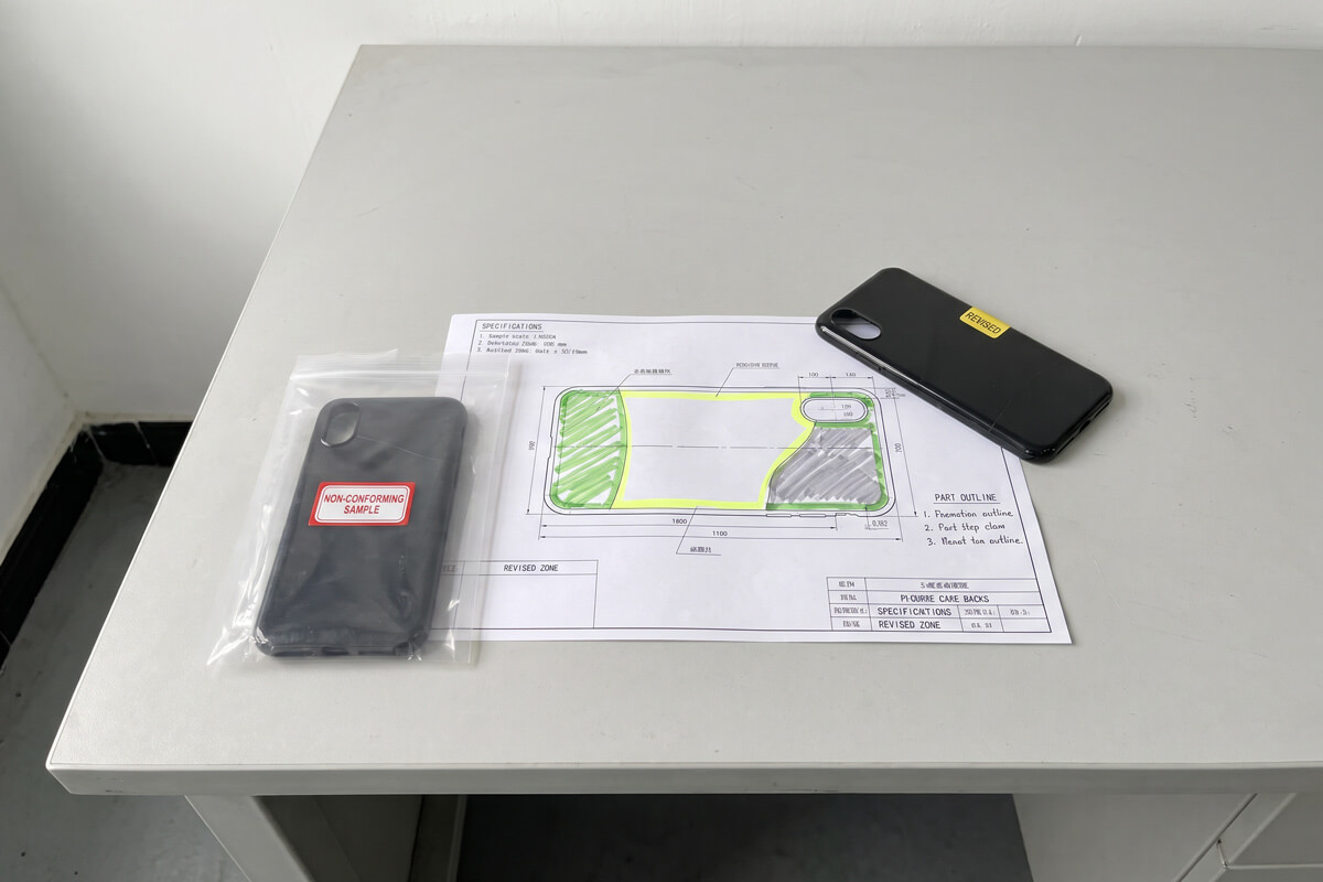
- 1Zone the surfaces. Mark Zone A (visible in use, no weld lines), Zone B (visible on inspection, short faint lines allowed) and Zone C (hidden).
- 2Mark the load paths. Snap-fits, hinges and screw bosses must not sit on a predicted weld line.
- 3Ask for weld locations in DFM. Review predicted gate and weld positions, by flow simulation or an experienced engineer’s review, and approve the gate position in writing.
- 4Review T1 samples under fixed light. Use the same distance, angle and lamp every time so approval does not depend on mood.
- 5Keep reference samples. Sign one accept sample and one reject sample and keep both with the tool to settle later batches.
That list costs an afternoon and saves several sample rounds.
Quick Diagnosis by Symptom
| What you see | Check this first |
|---|---|
| Deep, V-shaped notch at the seam | Venting at the convergence point, then mold temperature |
| Dark or colored streak along the seam | Colorant type (metallic or pearlescent), then gate position |
| Cracks at the line under load or during assembly | Part layout and gate position, packing pressure, fiber-filled grade |
| Seam on one cavity only, in a multi-cavity tool | That cavity’s vents, gate and cooling, not the global process |
For the wider defect list, see our overview of plastic molding defects and remedies.
Frequently Asked Questions
What causes weld lines in injection molding?
Weld lines are caused by two melt fronts meeting after they have cooled, or with air trapped between them. The common triggers are:
- Melt or mold temperature that is too low
- Injection speed that is too slow
- No vent at the convergence point
- Holes, inserts or multiple gates that split the flow
- Glass fibers, metallic flake or pearlescent pigment in the resin
How do you prevent weld lines in injection molding?
You cannot always prevent them, but you can relocate and reduce them. Work in this order:
- Move the gate or change the gate count so the line lands on a hidden surface
- Raise melt and mold temperature within the datasheet range
- Increase injection speed and packing pressure
- Add or improve venting at the weld location
- Use paint, texture or a different colorant to mask cosmetic marks
What is the difference between a weld line and a knit line?
Weld line and knit line are two names for the same defect. A meld line is a related seam where fronts merge at a shallow angle, typically above about 135 degrees, and it is usually stronger and far less visible.
Do weld lines weaken a plastic part?
Yes, often, but the loss depends on the resin and molding conditions. Glass-filled grades lose the most strength and PE or PP the least. Keep snap-fits, hinges and screw bosses away from predicted weld locations.
What temperature reduces weld lines?
Higher melt and mold temperatures reduce weld lines, but no single number fits every resin. Stay inside the datasheet range and change one setting at a time.
Can weld lines be removed after molding?
Cosmetic weld lines can be hidden after molding, but structural weakness cannot be repaired. Options for cosmetic marks:
- Painting the surface
- Adding texture
- Applying a decorative film
A seam on a load path needs a tool or resin fix.
Send your STEP file with the surface finish and quantity. We return a DFM note that flags likely weld line locations and proposes a gate position before any steel is cut. We sign an NDA before you share files.
Request a DFM reviewSend photos of the defect, the part drawing and your resin grade. We will tell you whether it is a gate, process or material problem, and what a fix would take.
Send us your samples