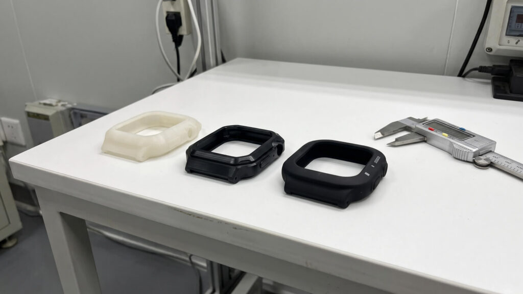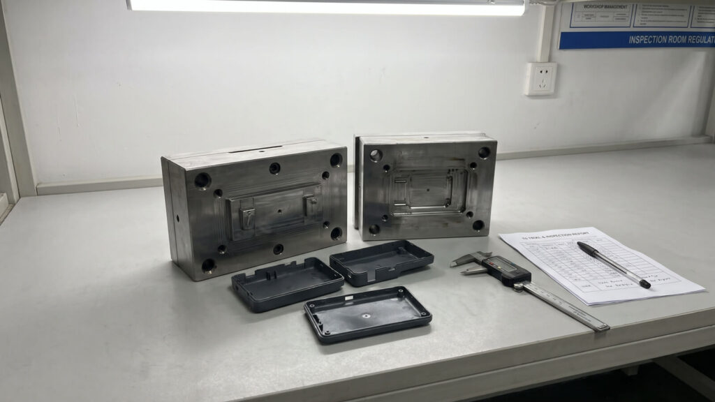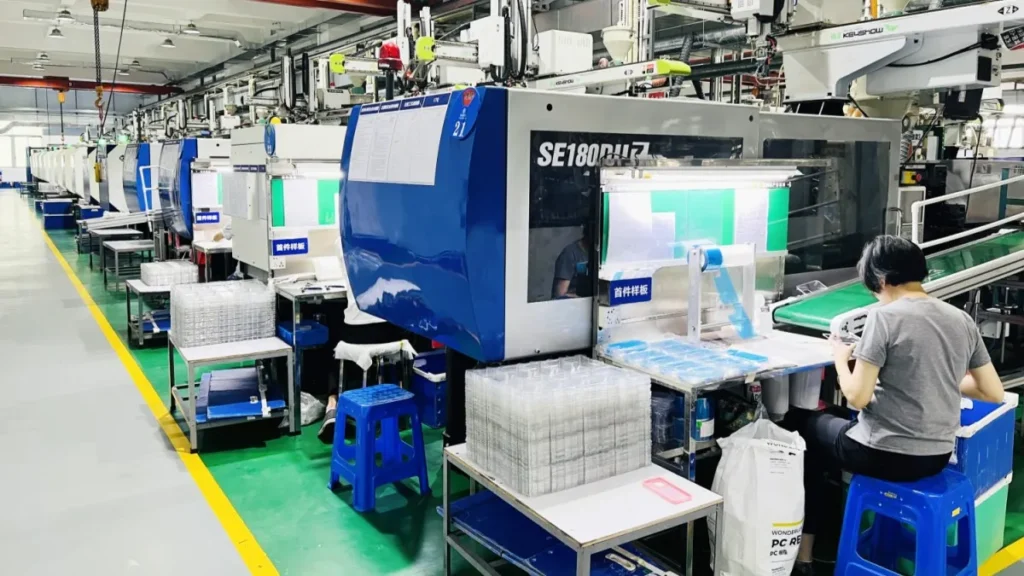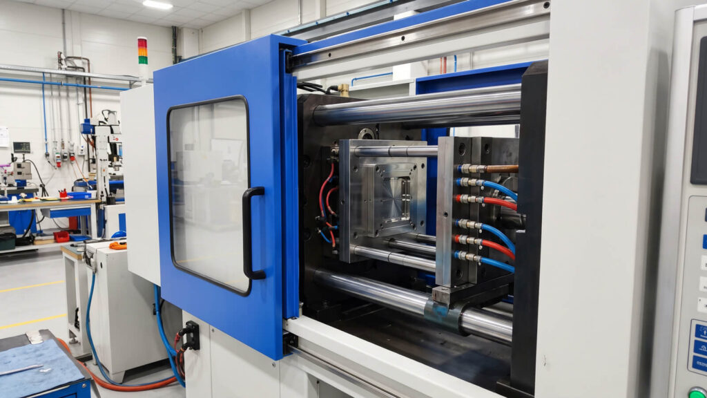


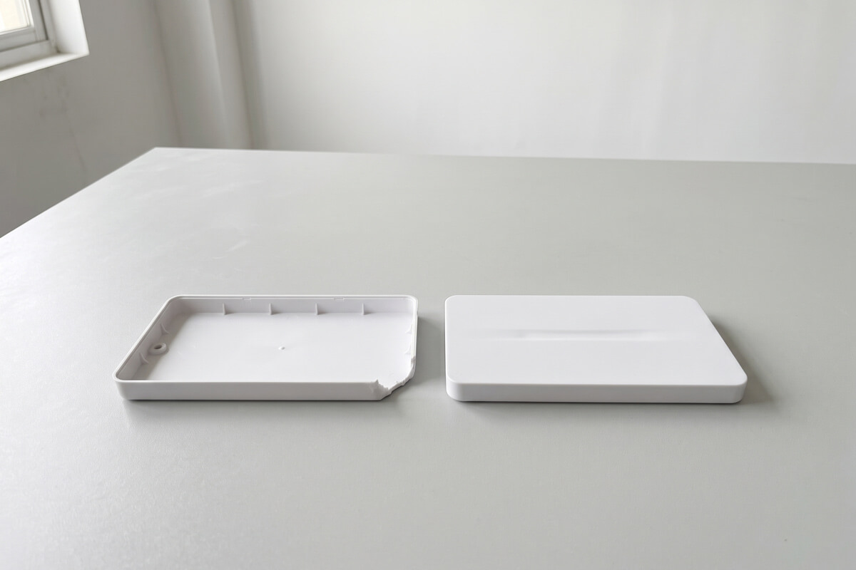
A short shot is a molded part that comes out incomplete because the melt stalled or froze before the cavity was full. The usual victims are thin walls, far corners, ribs and snap hooks at the end of the flow path. It is easy to see and hard to assign: the same missing corner can come from the machine, process, resin or tool.
Buyers meet it first at T1, the first trial samples. They do not need another generic cause list. They need to know whose problem it is, how to keep bad parts out of a shipment, and how to design the part so it stops happening. As a plastic injection molding manufacturerrunning plenty of thin-wall accessory tooling, we cover those three in order.
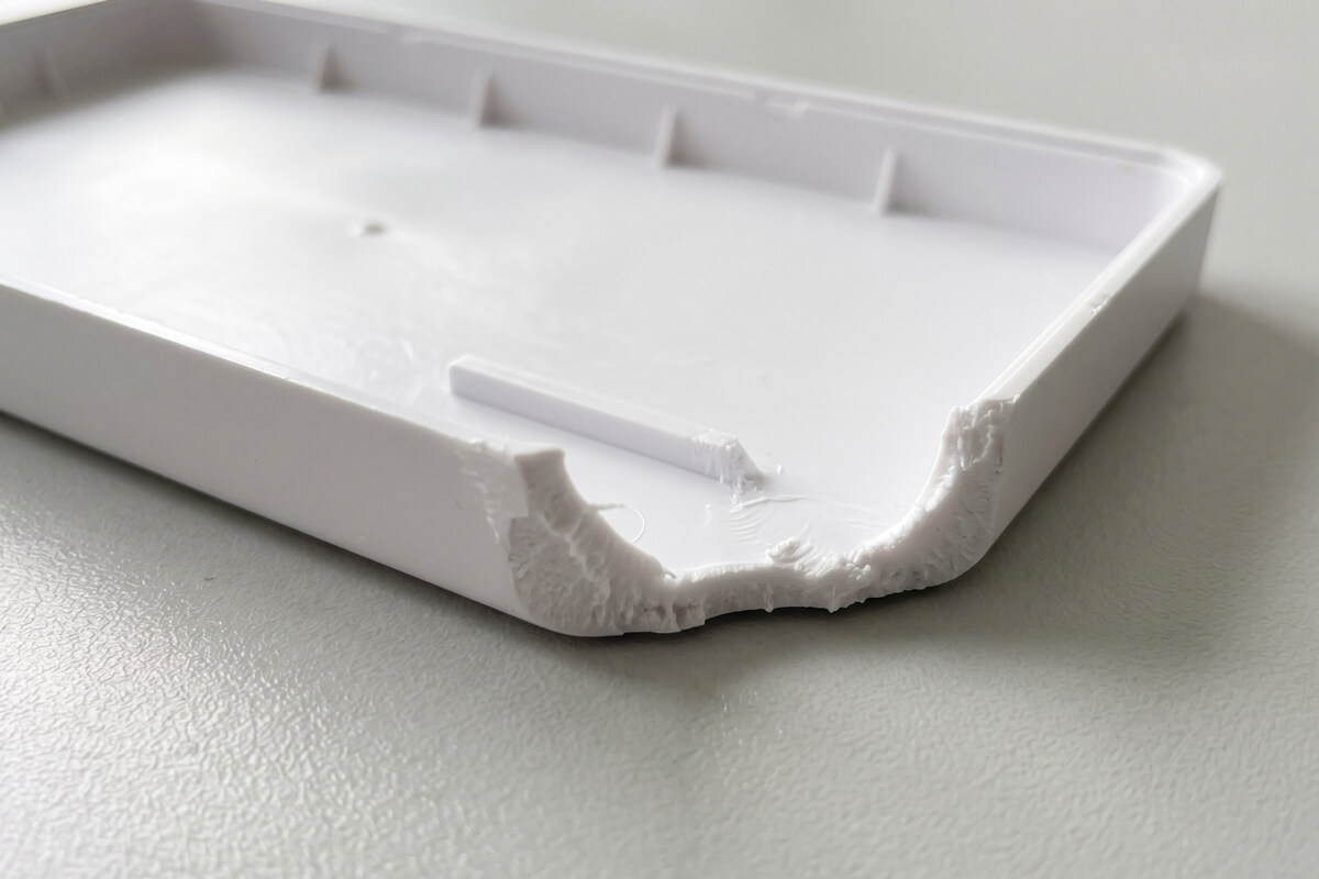
Pressure Limit or Venting? How to Settle It at T1
When a T1 sample comes back short, the molder blames the tool and the toolmaker blames the settings. You can end that argument with evidence from a short, structured trial.
Step 1: Make a fill-only part
Turn off pack and hold, then set the shot size so the part is about 99% full. Judging fill and pack separately, the idea behind decoupled molding, shows where the flow really stops. Run a few shots. If the stall point wanders, suspect material, machine or shot repeatability. If it lands on the same spot every time, the cause is in the geometry or the tool.
Step 2: Read the pressure curve against the limit
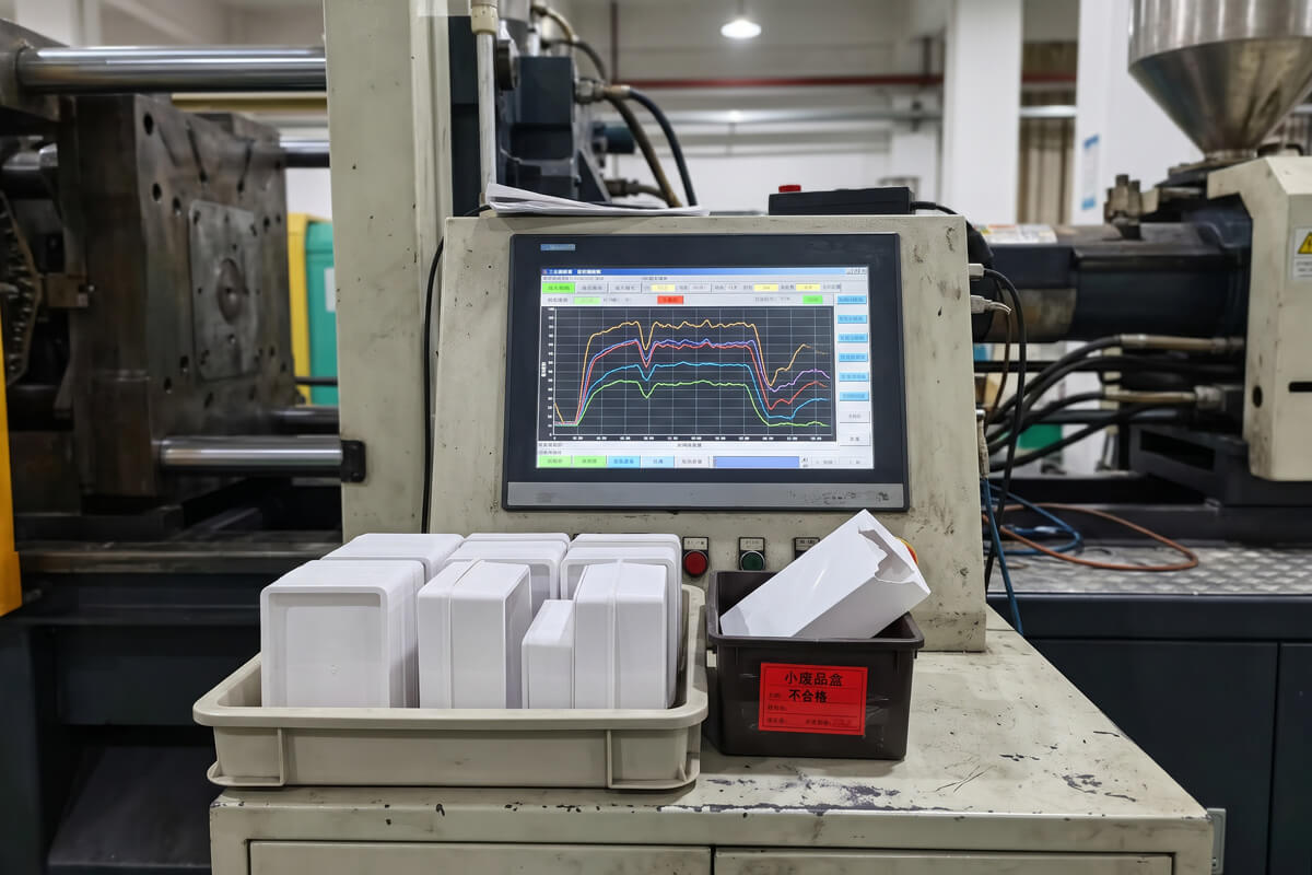
Pull up the injection pressure and velocity curves. If pressure flattens against the machine’s limit while velocity sags, the process is pressure-limited: the press cannot hold the set speed, so look at machine capacity, melt temperature, resin viscosity or a pressure-hungry runner and gate. If pressure has headroom and the part still stalls, pressure is not the bottleneck. Check actual melt temperature too, not just the setpoint, as Yizumi’s 2026 troubleshooting guidealso advises.
Step 3: Look for physical evidence at the last-fill point
One useful discriminator is to slow the last 10–20% of the fill. If the part gets fuller, air is escaping more easily and venting is the likely limit. If it gets worse, the shot is short of energy. Combine that with what the part and tool show:
| What you see | What it points to |
|---|---|
| Pressure plateaus at the limit and velocity drops | Machine or process: pressure-limited fill |
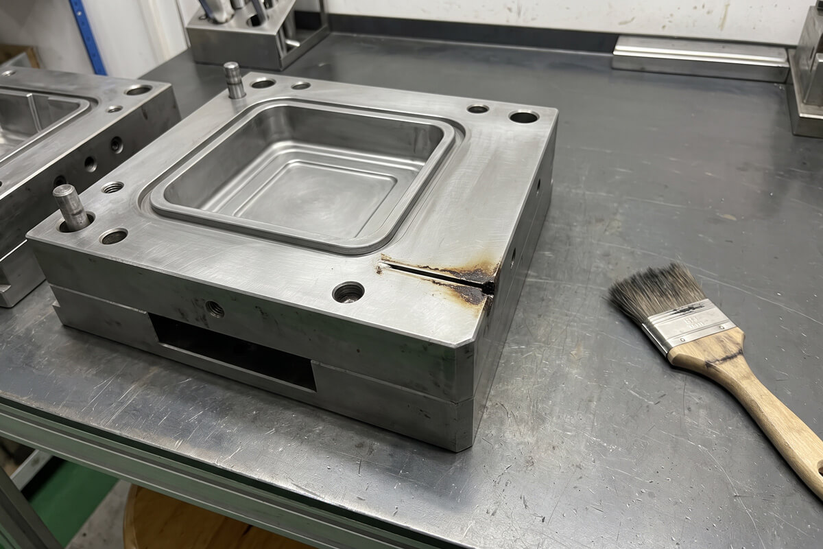
| Same last-fill spot short in every cavity, with a dark or burnt edge nearby | Mold: venting or flow length at that spot |
| Fuller part when the final fill slows down | Venting |
| Fills only when melt or mold temperature rises | Freeze-off: process window or a wall that is too thin |
| One cavity short in a multi-cavity tool | That cavity’s gate, vent or hot runner balance |
What to ask for in the T1 report
- Photos of the fill-only part from several shots, with the stall point marked
- Pressure and velocity curves with the machine limit shown
- Measured melt temperature, and photos of the vents before cleaning
- A written verdict naming the owner: process change or tool modification
If the verdict is the tool, a vent or gate revision is usually a modest steel job. On a rapid toolingprogram, our MUD route gets samples out in as little as 10 days, and larger changes move into our injection mold manufacturingworkflow.
Short Shots in a Production Batch: Where the Cost Hides
A short shot caught at T1 costs a trial. One that ships can stop your assembly line. The risk concentrates in thin-wall and multi-cavity tools, where one cavity that occasionally under-fills still puts a part in the box that looks right at a glance.
Where the defect is caught decides what it costs, so detection belongs in the press, not in someone’s eyes at the end of a shift.
Questions to ask a supplier before you place the order
- Are cavity pressure sensors fitted at the end of the flow path, one per cavity in the same position? An under-filled cavity shows a lower peak, so the shot can be flagged.
- Is there an automated vision or weight check at ejection, and can it reject by cavity?
- How are rejected parts separated from good ones, and how is a suspect lot traced back to cavity and shift?
- What is the containment plan if one escapes, and how is the remedy agreed?
The last question matters commercially. At YG Tech, quality anomalies follow a traceable-responsibility loop with a negotiated remedy, not a simple swap. We are ISO 9001 and ISO 13485 certified and have passed Amazon and Walmart factory audits, and our custom injection molding servicesteam can walk through the controls for your tool.
Designing Out Chronic Short Shots Without Adding Weight
When the same corner keeps stalling after the process is dialed in, the geometry is asking for more flow than the wall can deliver. Thin walls freeze before the melt arrives, and on slim lids and phone casebodies the wall is thin by design.
Start with the flow ratio
Flow ratio is the longest flow path divided by the wall thickness. RJG’s guideline, quoted by Mack Molding, is to stay under 150, and Mack designs to 100 for extra margin (Source: Mack Molding, 2024). In Mack’s example, a 21.75-inch path on a 0.16-inch wall gives about 136, which passes the standard but is split with a second gate to get under 100. A 36-inch path on the same wall gives 225 and needs a redesign. Mack’s gate rules: place the gate at the thickest wall, keep the flow short, and weigh the cosmetic cost.
Flow leaders: local thickness instead of a thicker wall
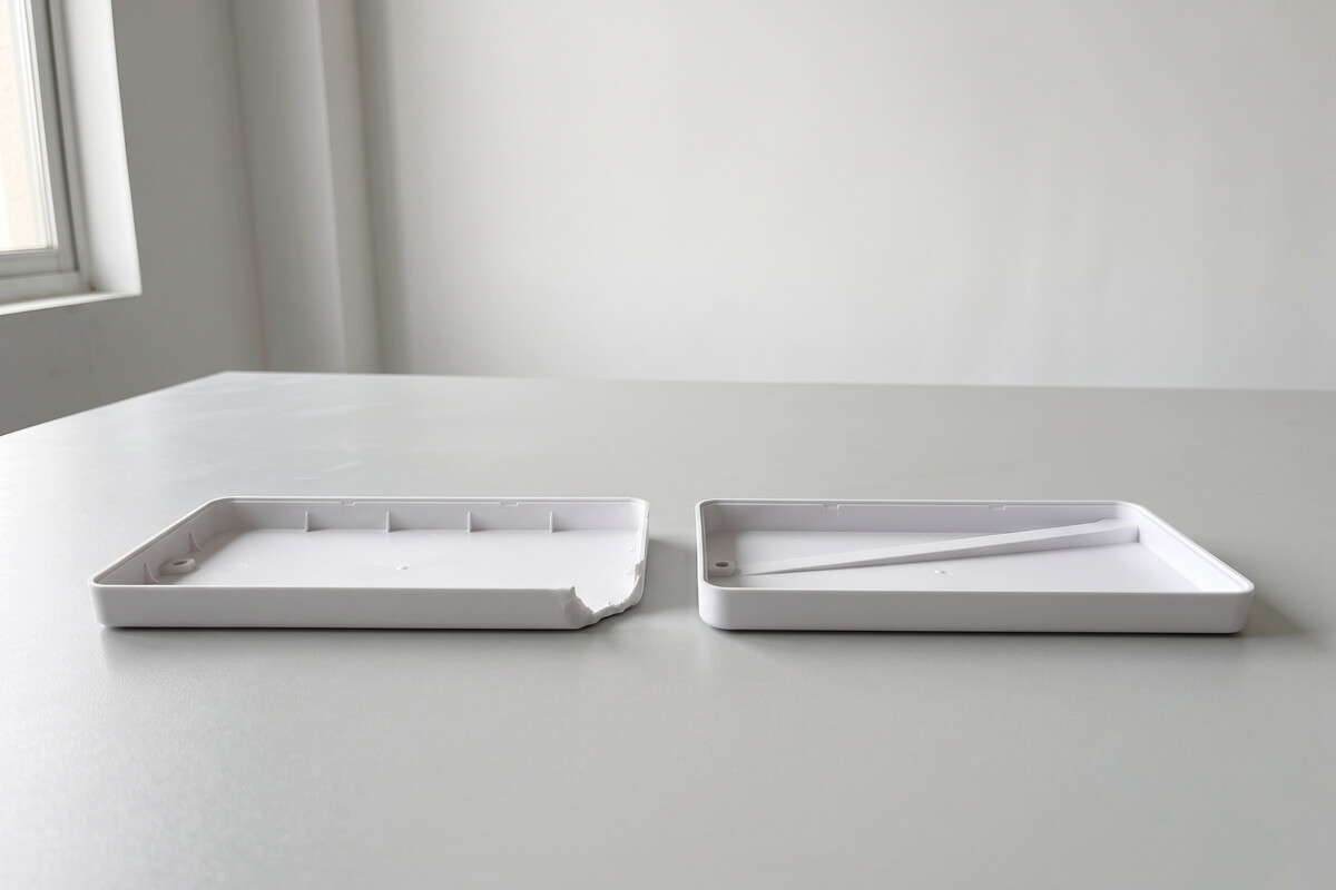
A flow leader is a shallow raised path on the non-show side that runs from the gate toward the last-fill area. Mack describes typical leaders as about 1 inch wide and 1 mm high with heavy draft, which lower the flow ratio, reduce shear and air pockets, and can remove the need for an extra gate. The weight math is what makes them attractive. Take an illustrative 120 × 60 mm lid with a 0.8 mm wall and a 130 mm longest flow path:
| Option | Wall at the flow path | Flow ratio | Added material |
|---|---|---|---|
| As designed | 0.8 mm | about 163 | 0% |
| Thicker wall everywhere | 1.1 mm | about 118 | +37.5% |
| 0.8 mm wall plus one flow leader, 10 mm wide and 0.3 mm high | 1.1 mm along the leader | about 118 along the leader | +6.3% |
Illustrative geometry for the arithmetic only; confirm any real part with flow simulation.
Start the leader at the gate and fade it out with generous draft so it does not print through on the show surface. Our guide on how to design for injection moldingcovers the wall-thickness basics.
Other levers worth a DFM review
- Move or add a gate. In a hot runner mold, valve gatescan shorten the path without adding visible marks.
- Put a vent at every last-fill point, including the tips of deep ribs.
- Move to a higher-flow resin grade, then re-approve shrinkage, strength and finish.
Frequently Asked Questions
What is a short shot in plastic injection molding?
A short shot is a molded part that is incomplete because the melt stalled or froze before filling the cavity. Typical signs are:
- A missing corner, edge or end, usually far from the gate
- Rounded, soft edges instead of a sharp break
- Ribs, bosses or hooks that are only partly formed
- A part that weighs less than a good one
What are the main causes of short shots in injection molding?
Short shots come from melt that loses momentum or meets resistance before the cavity is full. The causes group into four areas:
- Process:low injection speed, low melt or mold temperature, early switchover, insufficient shot size
- Mold:restricted venting, undersized gate or runner, a long flow path on a thin wall
- Material:low-flow resin, moisture, contamination, batch variation
- Machine:a pressure limit set too low, worn check ring, unstable cushion
How do you fix short shots during the injection molding process?
Fix them in a fixed order, changing one variable at a time:
- Make a fill-only part and adjust shot size until it is about 99% full
- Raise melt temperature and injection speed within the resin datasheet range
- Review the switchover point, then pack pressure once the cavity fills
- If the part still stalls at the same spot, add vents or enlarge the gate
Pressure alone can trade a short shot for flash.
Can poor mold venting cause a short shot?
Yes. Air that cannot escape builds back pressure at the end of fill and physically blocks the melt. Clues include:
- The same last-fill spot short in every cavity
- A burn mark or dark edge nearby
- A fuller part when the final fill slows down
Cleaning or adding vents at last-fill points usually cures it. See also bubbles in plastic injection molding.
How does resin melt flow index (MFI) affect short shot risk in thin-wall parts?
A higher MFI means lower viscosity, so the resin flows farther in a thin wall and short shots are less likely. MFI alone does not set the limit: it is measured at low shear, while injection shear is far higher, so ask for spiral-flow or viscosity data and check the flow ratio. A higher-flow grade can also change strength, shrinkage and finish, so re-approve samples. See our material selection guide.
What is the difference between a short shot and a sink mark?
A short shot is missing material, while a sink mark is a dent on a part that is otherwise complete. Check three things:
| Check | Short shot | Sink mark |
|---|---|---|
| Edges and features | Incomplete, rounded, partly formed | Fully formed |
| Weight versus a good part | Lower | About the same |
| Typical location | End of the flow path | Over a thick section, rib or boss |
Sink marks come from inadequate packing and shrinkage, not a failure to fill. Our overview of plastic molding defects and remedieshelps you write the right corrective action.
Send your STEP file with the target wall thickness and resin. We return a flow-ratio check and a vent and gate plan before any steel is cut, and we sign an NDA before you share files.